The A4988 is a complete microstepping motor driver module built around the Allegro A4988 DMOS microstepping driver IC with built-in translator. By accepting just two control signals — STEP and DIR — from a microcontroller, it independently handles all the phase sequencing, current regulation, and microstepping waveform generation required to drive a bipolar stepper motor smoothly and precisely.
Pinout
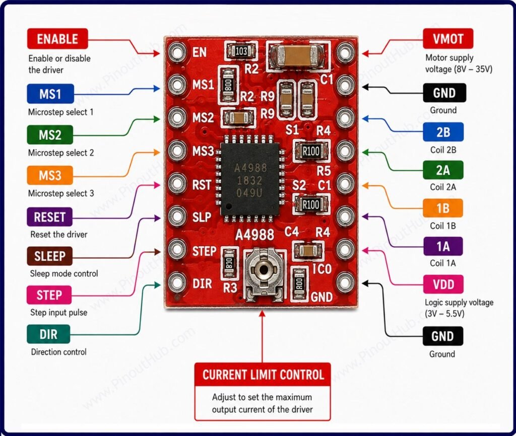
The A4988 module has 16 pins arranged in two rows of 8 on opposite sides of the board. The left row carries logic control and power signals; the right row carries motor output and power signals.
Left pin row (top to bottom)
| Pin | Name | Type | Description |
|---|---|---|---|
| 1 | ENABLE | Input | Active LOW — pull LOW to enable outputs; pull HIGH to disable all motor outputs and enter low-power idle |
| 2 | MS1 | Input | Microstepping resolution select bit 1 — see microstepping table |
| 3 | MS2 | Input | Microstepping resolution select bit 2 — see microstepping table |
| 4 | MS3 | Input | Microstepping resolution select bit 3 — see microstepping table |
| 5 | RESET | Input | Active LOW reset — pull LOW to reset the translator to initial home state; must be pulled HIGH for normal operation |
| 6 | SLEEP | Input | Active LOW sleep — pull LOW to enter low-power sleep mode; pull HIGH for normal operation |
| 7 | STEP | Input | Step input — one rising edge advances the motor one microstep in the direction set by DIR |
| 8 | DIR | Input | Direction input — HIGH for one direction; LOW for the opposite direction |
Right pin row (top to bottom)
| Pin | Name | Type | Description |
|---|---|---|---|
| 1 | VMOT | Power | Motor supply voltage — 8V to 35V DC; decouple with 100µF capacitor to GND |
| 2 | GND | Power | Motor supply ground |
| 3 | 2B | Output | Stepper motor coil 2 terminal B |
| 4 | 2A | Output | Stepper motor coil 2 terminal A |
| 5 | 1A | Output | Stepper motor coil 1 terminal A |
| 6 | 1B | Output | Stepper motor coil 1 terminal B |
| 7 | VDD | Power | Logic supply voltage — 3.3V to 5V |
| 8 | GND | Power | Logic supply ground |
RESET and SLEEP: On most modules, RESET and SLEEP are connected together via a solder bridge or trace, keeping them both HIGH by default. If exposed as separate pins, both must be pulled HIGH for normal operation — leaving either floating can prevent the motor from moving.
ENABLE: The ENABLE pin is active LOW and is pulled LOW by default on most modules, keeping the outputs always enabled. Driving it HIGH disables all motor outputs and reduces current consumption, useful for allowing the motor to be moved by hand during idle periods.
Microstepping Mode Table
| MS1 | MS2 | MS3 | Step Mode |
|---|---|---|---|
| LOW | LOW | LOW | Full step |
| HIGH | LOW | LOW | Half step (1/2) |
| LOW | HIGH | LOW | Quarter step (1/4) |
| HIGH | HIGH | LOW | Eighth step (1/8) |
| HIGH | HIGH | HIGH | Sixteenth step (1/16) |
All three MS pins have internal pull-down resistors — leaving them unconnected defaults to full-step mode. Higher microstepping modes produce smoother and quieter motor motion at the cost of reduced torque and higher step pulse frequency requirements from the microcontroller.
Module Construction
A4988 IC A 28-pin QFN package (5 × 5mm) with an exposed thermal pad on the underside. Contains two full N-channel DMOS H-bridges, the built-in translator with microstepping table, fixed off-time PWM current regulator, automatic decay mode selection, and overcurrent and thermal protection circuitry.
Current Sense Resistors Two 0.1Ω precision resistors — one per motor coil — in series with the low-side of each H-bridge. The voltage across these resistors is monitored by the IC to regulate coil current to the level set by VREF. The current limit formula is: I = VREF ÷ (8 × RS).
Current Limiting Potentiometer A small trimmer potentiometer on the board that sets the VREF voltage, which in turn sets the maximum coil current. Must be adjusted before first use. The VREF voltage is measured at the wiper of the potentiometer with a multimeter while the module is powered.
Bypass Capacitors Small ceramic capacitors on the VDD and VMOT supply pins that filter high-frequency switching noise. These are insufficient on their own for inductive spike suppression on VMOT — an external 100µF bulk capacitor across VMOT and GND is mandatory.
RESET / SLEEP Jumper On most modules, a solder bridge or PCB trace connects the RESET and SLEEP pins together, pulling both HIGH by default through an internal pull-up. This keeps the driver always active when powered.
Specifications
| Parameter | Value |
|---|---|
| Supply | |
| Motor Supply Voltage (VMOT) | 8V – 35V DC |
| Logic Supply Voltage (VDD) | 3.3V – 5V |
| Output | |
| Peak Output Current | ±2A per coil |
| Continuous Output Current | ±1A per coil (no heatsink) |
| Microstepping | |
| Step Modes | Full / 1/2 / 1/4 / 1/8 / 1/16 |
| Steps per Revolution (1.8° motor, 1/16) | 3200 |
| Control | |
| Control Interface | STEP / DIR |
| Logic Input Levels | 3.3V / 5V TTL |
| ENABLE | Active LOW |
| RESET | Active LOW |
| SLEEP | Active LOW |
| Protection | |
| Overcurrent Protection | Yes |
| Thermal Shutdown | Yes |
| Under-Voltage Lockout | Yes |
| General | |
| Operating Temperature | −40°C to +85°C |
| IC Package | 28-pin QFN, 5 × 5mm |
| RoHS | Compliant |
Helpful resources
- Download the datasheet: here
- A4988 with Arduino
- A4988 with ESP32
- A4988 with Raspberry Pi