The L293D motor driver module is a compact breakout board built around the L293D quad push-pull motor driver IC that controls the speed and direction of two DC motors or one bipolar stepper motor simultaneously. By accepting standard TTL logic level signals from a microcontroller and switching motor power independently through two internal H-bridge circuits, it acts as the bridge between low-power control signals and higher-power motor loads.
Pinout
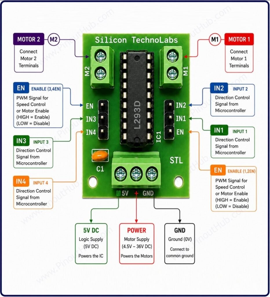
The L293D module exposes connections through two 3-pin logic headers on the left and right sides of the IC, two motor output screw terminals on the top, and a 3-pin power screw terminal at the bottom.
Left logic header (top to bottom)
| Pin | Name | Type | Description |
|---|---|---|---|
| 1 | EN | Input | Enable for Bridge 2 (3,4EN) — HIGH enables Motor 2; connect PWM signal here for speed control |
| 2 | IN3 | Input | Direction control input 3 for Motor 2 |
| 3 | IN4 | Input | Direction control input 4 for Motor 2 |
Right logic header (top to bottom)
| Pin | Name | Type | Description |
|---|---|---|---|
| 1 | IN2 | Input | Direction control input 2 for Motor 1 |
| 2 | IN1 | Input | Direction control input 1 for Motor 1 |
| 3 | EN | Input | Enable for Bridge 1 (1,2EN) — HIGH enables Motor 1; connect PWM signal here for speed control |
Motor output screw terminals (top)
| Terminal | Name | Description |
|---|---|---|
| M2 | Motor 2 | Connect both terminals of Motor 2 here |
| M1 | Motor 1 | Connect both terminals of Motor 1 here |
Power screw terminals (bottom)
| Terminal | Name | Type | Description |
|---|---|---|---|
| 5V | VCC1 | Power | Logic supply — connect to 5V DC to power the IC |
| + | VCC2 | Power | Motor supply — connect to 4.5V to 36V DC to power the motors |
| GND | GND | Power | Ground — common for both logic and motor supply |
Module construction
L293D IC A 16-pin DIP package containing two complete full H-bridge circuits, internal clamp diodes on all four output pins, separate logic and motor supply rails, and internal thermal shutdown. All direction and enable logic, push-pull switching transistors, and clamp diodes are integrated within this single IC.
Internal Clamp Diodes Eight internal Schottky clamp diodes — two per output pin — absorb back-EMF voltage spikes from motor windings when they are switched off. This eliminates the need for any external freewheeling diodes on the module board.
Decoupling Capacitors Ceramic and electrolytic capacitors on the VCC1 and VCC2 supply rails that filter high-frequency noise and absorb current surges when both H-bridges switch simultaneously, preventing supply rail collapse that would otherwise cause microcontroller resets.
Power Screw Terminals Screw terminal blocks for connecting the motor supply (VCC2), logic supply (VCC1), and ground. Allow secure connection of heavier gauge wiring for motor power.
Motor Output Screw Terminals Four screw terminal connections — two per motor — for connecting DC motor leads or stepper motor coil wires securely.
Logic Control Header A 6-pin header exposing IN1, IN2, ENA, IN3, IN4, and ENB for direct connection to microcontroller GPIO and PWM pins.
Specifications
| Parameter | Value |
|---|---|
| Supply | |
| Motor Supply Voltage (VCC2) | 4.5V – 36V DC |
| Logic Supply Voltage (VCC1) | 5V (4.5V – 7V) |
| Quiescent Supply Current (VCC1) | 100µA typical |
| Output | |
| Continuous Output Current | 600mA per channel |
| Peak Output Current | 1.2A per channel |
| Output Voltage Drop | ~1.8V per H-bridge |
| PWM Switching Frequency | Up to 5kHz |
| Protection | |
| Internal Clamp Diodes | Yes (8 diodes — 2 per output pin) |
| Thermal Shutdown | Yes (internal) |
| Control | |
| Logic Input Levels | TTL compatible |
| Enable Pins | ENA (Motor A) / ENB (Motor B) |
| Number of H-Bridges | 2 |
| Motor Channels | 2 DC motors / 1 bipolar stepper motor |
| General | |
| Operating Temperature | −40°C to +150°C |
| Driver IC Package | 16-pin DIP |
| RoHS | Compliant |
Helpful Resources
- Download the datasheet: here
- L293D Module with Arduino
- L293D Module with Raspberry Pi