The DRV8825 is a high-performance microstepping motor driver module built around the Texas Instruments DRV8825 IC that controls bipolar stepper motors using just two signals — STEP and DIR — from a microcontroller. By handling all phase sequencing, PWM current regulation, and microstepping waveform generation internally, it drives a stepper motor smoothly and precisely without requiring complex sequencing code on the host side.
Pinout
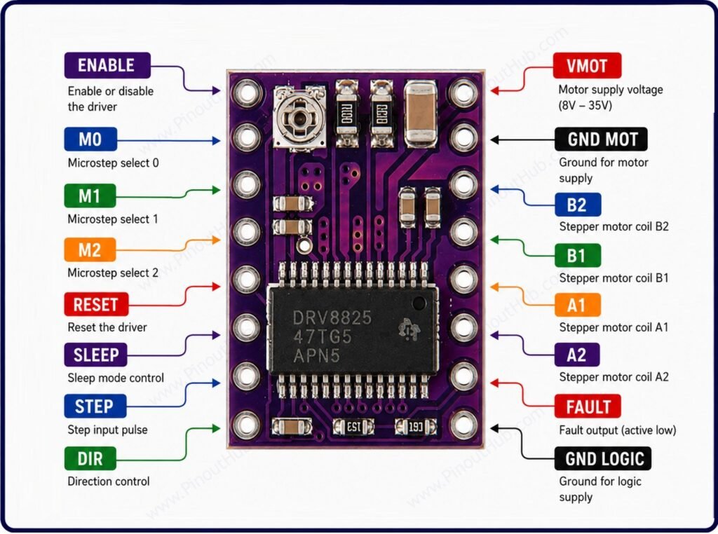
The DRV8825 module has 16 pins arranged in two rows of 8 on opposite sides of the board — the same layout as the A4988. The left row carries logic control signals; the right row carries motor outputs and power.
Left pin row (top to bottom)
| Pin | Name | Type | Description |
|---|---|---|---|
| 1 | ENABLE | Input | Active LOW — pull LOW to enable outputs; pull HIGH to disable all motor outputs |
| 2 | M0 | Input | Microstepping resolution select bit 0 — see microstepping table |
| 3 | M1 | Input | Microstepping resolution select bit 1 — see microstepping table |
| 4 | M2 | Input | Microstepping resolution select bit 2 — see microstepping table |
| 5 | RESET | Input | Active LOW reset — pull LOW to reset the indexer to home state; must be HIGH for normal operation |
| 6 | SLEEP | Input | Active LOW sleep — pull LOW to enter low-power sleep mode; pull HIGH for normal operation |
| 7 | STEP | Input | Step input — one rising edge advances the motor one microstep in the direction set by DIR |
| 8 | DIR | Input | Direction input — HIGH for one direction; LOW for the opposite |
Right pin row (top to bottom)
| Pin | Name | Type | Description |
|---|---|---|---|
| 1 | VMOT | Power | Motor supply voltage — 8.2V to 45V DC; decouple with 100µF capacitor to GND |
| 2 | GND | Power | Motor supply ground |
| 3 | B2 | Output | Stepper motor coil B terminal 2 |
| 4 | B1 | Output | Stepper motor coil B terminal 1 |
| 5 | A1 | Output | Stepper motor coil A terminal 1 |
| 6 | A2 | Output | Stepper motor coil A terminal 2 |
| 7 | FAULT | Output | Fault output — goes active LOW when overcurrent or thermal shutdown is triggered |
| 8 | VDD | Power | Logic supply voltage — 3.3V to 5V |
RESET and SLEEP: On most modules, RESET and SLEEP are connected together and pulled HIGH by default. Both must be HIGH for normal operation — if exposed as separate pins, neither should be left floating.
FAULT pin: The FAULT pin is open-drain and active LOW. It goes LOW when the IC detects an overcurrent condition or thermal shutdown. On the DRV8825, FAULT is also internally connected to SLEEP — a fault condition pulls SLEEP LOW and disables the driver until the fault clears or the module is reset. Connect FAULT to a GPIO interrupt pin on the microcontroller to detect and handle fault conditions in firmware.
DECAY pin: Some module variants expose a DECAY pin that selects the current decay mode — floating or LOW selects mixed decay; HIGH selects slow decay. Most modules connect this pin to GND by default, enabling mixed decay.
Microstepping mode table
| M0 | M1 | M2 | Step Mode |
|---|---|---|---|
| LOW | LOW | LOW | Full step |
| HIGH | LOW | LOW | Half step (1/2) |
| LOW | HIGH | LOW | Quarter step (1/4) |
| HIGH | HIGH | LOW | Eighth step (1/8) |
| LOW | LOW | HIGH | Sixteenth step (1/16) |
| HIGH | LOW | HIGH | Thirty-second step (1/32) |
All three M0, M1, and M2 pins have internal pull-down resistors — leaving them unconnected defaults to full-step mode. At 1/32 microstepping, a standard 1.8° stepper motor advances 200 × 32 = 6400 microsteps per revolution, giving extremely fine position resolution.
Module Construction
DRV8825 IC A 28-pin HTSSOP package containing two full N-channel MOSFET H-bridges, built-in microstepping indexer, fixed-frequency PWM current regulator, three selectable decay modes, FAULT output logic, and overcurrent and thermal protection circuitry.
Current Sense Resistors Two precision resistors — one per coil — in series with the low-side of each H-bridge. Used by the IC to monitor coil current and regulate it to the ITRIP threshold. With 0.1Ω sense resistors, the current limit formula is: I = VREF ÷ 2.
Current Limiting Potentiometer A trimmer potentiometer that sets the VREF voltage, directly setting the maximum coil current limit. Must be adjusted before first use. VREF is measured at the wiper of the potentiometer with the module powered but no motor connected.
Low-ESR Ceramic Bypass Capacitors Small ceramic capacitors on VMOT that filter high-frequency switching noise. These are insufficient for inductive spike suppression — a 100µF external electrolytic capacitor across VMOT and GND is mandatory.
RESET / SLEEP Connection On most modules, RESET and SLEEP are bridged together and pulled HIGH through an internal resistor, keeping the driver active whenever VDD is supplied.
Specifications
| Parameter | Value |
|---|---|
| Supply | |
| Motor Supply Voltage (VMOT) | 8.2V – 45V DC |
| Logic Supply Voltage (VDD) | 3.3V – 5V |
| Output | |
| Peak Output Current | 2.5A per coil |
| Continuous Output Current | 1.5A per coil (no heatsink) |
| Microstepping | |
| Step Modes | Full / 1/2 / 1/4 / 1/8 / 1/16 / 1/32 |
| Steps per Revolution (1.8° motor, 1/32) | 6400 |
| Control | |
| Control Interface | STEP / DIR |
| Logic Input Levels | 3.3V / 5V TTL |
| ENABLE | Active LOW |
| RESET | Active LOW |
| SLEEP | Active LOW |
| FAULT | Active LOW output |
| Decay Modes | Slow / Fast / Mixed |
| Protection | |
| Overcurrent Protection | Yes |
| Thermal Shutdown | Yes (~150°C) |
| Under-Voltage Lockout | Yes |
| General | |
| Operating Temperature | −30°C to +85°C |
| IC Package | 28-pin HTSSOP |
| RoHS | Compliant |
Helpful Resources
- Download the datasheet: here
- DRV8825 with Arduino
- DRV8825 with ESP32
- DRV8825 with Raspberry Pi PICO