The ULN2003 stepper motor driver module is a simple unipolar stepper motor driver board built around the ULN2003A Darlington transistor array IC. By amplifying the low-current GPIO signals from a microcontroller into the higher-current drive signals required by unipolar stepper motor coils, it acts as the interface between a microcontroller and a stepper motor without requiring any additional components.
Pinout
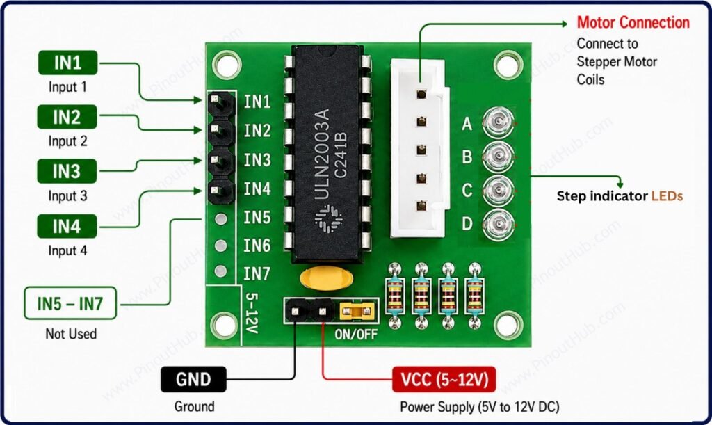
The ULN2003 stepper motor driver module typically has a 4-pin control header (IN1–IN4) for connection to a microcontroller, a 5-pin motor connector for connecting a stepper motor such as the 28BYJ-48, and separate VCC and GND power connections.
| Pin / Connection | Label | Function |
|---|---|---|
| Input 1 | IN1 | Stepper motor control input 1 |
| Input 2 | IN2 | Stepper motor control input 2 |
| Input 3 | IN3 | Stepper motor control input 3 |
| Input 4 | IN4 | Stepper motor control input 4 |
| Power | VCC / + | Motor power supply |
| Ground | GND / − | Ground connection |
| Motor Pin 1 | A | Motor coil connection |
| Motor Pin 2 | B | Motor coil connection |
| Motor Pin 3 | C | Motor common connection |
| Motor Pin 4 | D | Motor coil connection |
| Motor Pin 5 | E | Motor coil connection |
Module Construction
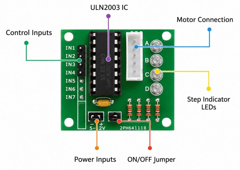
ULN2003A IC
A 16-pin DIP IC containing seven Darlington NPN transistor pairs. Each input has an internal resistor, and each output includes an internal clamp diode connected to the COM pin. Four channels are commonly used to drive the four phases of a 28BYJ-48 stepper motor, while the remaining three channels can be used for other loads.
4 Coil Indicator LEDs
Four indicator LEDs provide visual feedback for the four motor-driving channels. They illuminate according to the switching state of the corresponding ULN2003A outputs, making it easy to observe the stepping sequence.
5-Pin Motor Connector
A 5-pin motor connector is provided for connecting a compatible 5-wire stepper motor, such as the 28BYJ-48. On many modules, the connector is keyed to help prevent incorrect insertion.
Power Connections
The module provides VCC and GND connections for supplying power to the driver and connected motor. Depending on the module version, these connections may be provided through a screw terminal, header pins, or another connector arrangement.
ON/OFF Jumper
Some ULN2003 modules include a jumper that controls the motor power connection. However, this feature is not present on every ULN2003 module, so it should only be described if the specific board includes it.
Internal Freewheeling Diodes
The ULN2003A contains seven internal clamp diodes, with one associated with each Darlington output. These provide a path for inductive current and help protect the transistor outputs from voltage spikes generated by inductive loads such as motor coils. External flyback diodes are therefore generally unnecessary when the IC is used as intended.
Decoupling Capacitor
Many ULN2003 modules include a capacitor across the power supply to help reduce supply-voltage fluctuations and switching noise. The capacitor type and value can vary between module versions.
Specifications
| Parameter | Value |
|---|---|
| Supply | |
| Motor Supply Voltage (VCC) | 5V – 12V DC |
| Output (per channel) | |
| Maximum Sink Current | 500mA |
| Maximum Output Voltage | 50V |
| Darlington Gain (hFE) | ~1000 |
| Output Saturation Voltage | ~1V at 350mA |
| Input | |
| Logic Input Levels | TTL / 3.3V / 5V |
| Input Resistor | 2.7kΩ (internal) |
| Protection | |
| Internal Freewheeling Diodes | Yes (one per channel) |
| Module Features | |
| Stepper Control Inputs | IN1 – IN4 |
| Auxiliary Inputs | IN5 – IN7 |
| Coil Indicator LEDs | 4 (one per coil) |
| Motor Connector | 5-pin JST |
| ON/OFF Jumper | Yes |
| General | |
| Compatible Motor | 28BYJ-48 (unipolar) |
| Compatible Boards | Arduino, ESP32, Raspberry Pi |
| IC Package | DIP-16 |
Helpful Resources
- Download the datasheet: here
- ULN2003 with Arduino
- ULN2003 with ESP32
- ULN2003 with Raspberry Pi