The PCA9685 is a 16-channel 12-bit PWM controller module built around the NXP PCA9685 IC that generates up to 16 independent PWM signals over a single I²C connection. By offloading all PWM generation to the dedicated IC, it frees every GPIO pin on the host microcontroller — allowing a single I²C connection to control up to 16 servos, LEDs, or other PWM-driven devices simultaneously.
Pinout
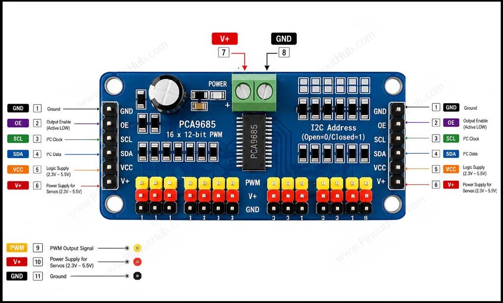
The bare PCA9685 IC is a 28-pin SSOP or HVQFN package and is not breadboard-compatible. It is used on a breakout module in virtually all maker applications. The breakout module exposes the I²C and control pins through a header, provides 16 three-pin servo/PWM output headers, and includes a screw terminal for external servo power.
| Pin | Function |
|---|---|
| GND | Ground |
| OE | Output Enable, active LOW |
| SCL | I²C clock |
| SDA | I²C data |
| VCC | Logic supply, typically 2.3–5.5 V |
| V+ | External supply for connected servos/loads |
| PWM 0–15 | 16 PWM output channels |
| GND | Ground for output channels |
| A0–A5 | I²C address configuration |
entical control header on the opposite end of the board for daisy-chaining a second PCA9685 module. The SDA, SCL, VCC, and GND of the downstream module connect to this header.
Module construction
PCA9685 IC A 28-pin SSOP or HVQFN package containing the 16-channel PWM generator, 12-bit counter, programmable prescaler, internal 25MHz oscillator, EXTCLK input, I²C Fast-mode Plus interface, power-on reset circuit, and output enable logic.
16 Three-Pin Servo Headers Sixteen sets of three-pin headers in standard servo connector pitch (2.54mm), each carrying GND, V+, and PWM in the standard servo wire order. Servos plug directly into these headers without any additional wiring.
I²C Pull-up Resistors Onboard 10kΩ pull-up resistors on SDA and SCL hold the lines HIGH when idle. These are present on most breakout modules; when chaining multiple modules, all but one set of pull-ups should be disabled to prevent bus loading.
A0–A5 Address Solder Pads Six solder bridge pads on the board, each connecting an address pin to VCC when bridged. The combination of bridged pads sets the module’s I²C address within the 0x40–0x7F range.
External Power Screw Terminal A two-terminal screw connector for supplying 5V–6V external power to connected servos. This rail is completely separate from the VCC logic supply and must be connected to an external supply capable of providing sufficient current for all connected servos simultaneously — typically 1A–3A depending on servo count and load.
Onboard 10µF Capacitor A bulk decoupling capacitor on the V+ external power rail that absorbs current surges when multiple servos move simultaneously. Without it, voltage dips on the V+ rail can cause servo jitter and I²C communication errors.
Specifications
| Parameter | Value |
|---|---|
| Supply | |
| Logic Supply Voltage (VCC) | 2.3V – 5.5V |
| External Power (V+) | 5V – 6V DC |
| PWM | |
| Output Channels | 16 |
| PWM Resolution | 12-bit (4096 steps) |
| PWM Frequency Range | 24Hz – 1526Hz |
| Duty Cycle Range | 0% – 100% |
| Output | |
| Output Sink Current | 25mA per channel |
| Output Source Current | 10mA per channel |
| Interface | |
| Communication | I²C Fast-mode Plus |
| I²C Speed | Up to 1MHz |
| I²C Address Range | 0x40 – 0x7F |
| Cascadable Modules | Up to 62 |
| Clock | |
| Internal Oscillator | 25MHz |
| External Clock | Up to 50MHz (EXTCLK) |
| General | |
| Output Enable (OE) | Active LOW |
| Power-On Reset | Yes |
| Software Reset | Yes (I²C General Call) |
| Operating Temperature | −40°C to +85°C |
| IC Package | 28-pin SSOP / HVQFN28 |
| RoHS | Compliant |
Helpful resources
- Download the datasheet: here
- PCA9685 with Arduino
- PCA9685 with ESP32
- PCA9685 with Raspberry Pi