The MAX30102 is a high-sensitivity integrated pulse oximeter and heart rate biosensor that combines a red LED, an infrared LED, a photodetector, optical elements, and low-noise analog front-end electronics with ambient light rejection into a single compact package.
By measuring the absorption of red and infrared light passing through living tissue, it can determine both blood oxygen saturation (SpO₂) and heart rate (BPM) and report all data digitally over I²C.
Pinout
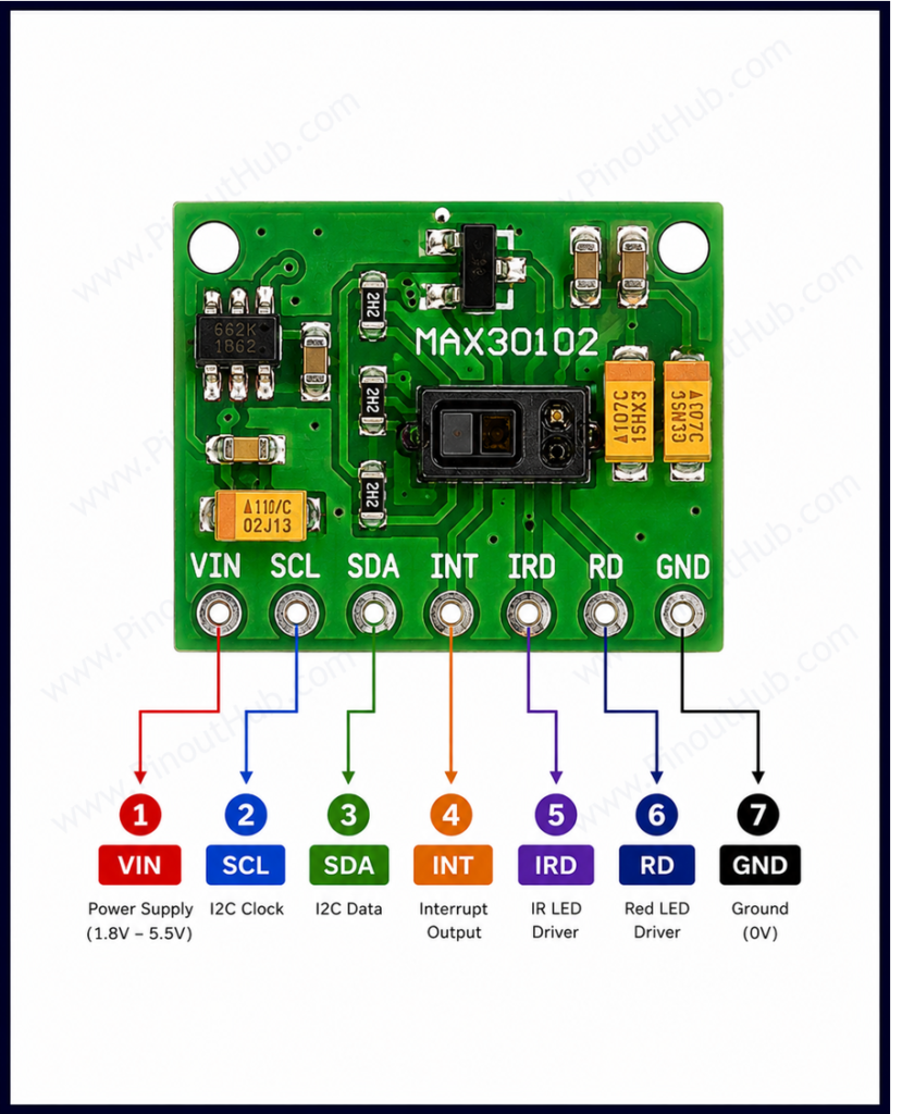
The bare MAX30102 IC is a 14-pin optical LGA package and is not breadboard-compatible. It is used on a breakout module in virtually all maker applications. Most breakout boards include onboard voltage regulators to generate both the 1.8V core and 3.3V LED supplies from a single 3.3V–5V input, and expose five or six pins through a header.
Breakout module pinout (6-pin header)
| Pin | Name | Type | Description |
|---|---|---|---|
| 1 | VIN | Power | Supply input — 3.3V to 5V |
| 2 | GND | Power | Ground |
| 3 | SCL | Input | I²C clock line — connect to microcontroller SCL |
| 4 | SDA | I/O | I²C data line — connect to microcontroller SDA |
| 5 | INT | Output | Interrupt output — active LOW, open-drain |
| 6 | RD | Output | Optional — routes the onboard regulated 3.3V to an external pin on some module variants |
I²C address: The MAX30102 has a single fixed I²C address of 0x57. It cannot be changed. Only one MAX30102 can be on the same I²C bus at a time without an I²C multiplexer.
INT pin: The INT pin is open-drain and requires a pull-up resistor — most breakout boards include one. It is active LOW, meaning it is pulled LOW by the sensor when an interrupt condition is met. Interrupt sources include FIFO almost full, new FIFO data ready, ambient light cancellation overflow, and die temperature conversion ready. Each interrupt source can be independently enabled or disabled via the interrupt enable registers.
MAX30102 Module Construction
MAX30102 Sensor IC A 14-pin optical LGA package integrating the red LED, infrared LED, photodetector, 18-bit ADC, ambient light cancellation circuit, FIFO buffer, die temperature sensor, and I²C interface logic — all in a 5.6 × 3.3 × 1.55mm package. The optical window on the top surface must be kept clean and free of obstruction.
1.8V LDO Voltage Regulator (TLV70018) Generates the 1.8V core supply required by the MAX30102 IC from the module VIN supply. Present on most breakout boards.
3.3V LDO Voltage Regulator (AP2112K) Generates the 3.3V VLED+ supply required by the internal LEDs from the module VIN supply. Allows the module to operate from a 3.3V or 5V host supply without any external regulation.
I²C Pull-up Resistors Onboard pull-up resistors on the SDA and SCL lines — typically 4.7kΩ — hold them at a high logic level when idle, as required by the I²C protocol.
Decoupling Capacitors Bypass capacitors on the VDD and VLED+ supply pins, placed close to the IC, suppress high-frequency supply noise. Clean supply rails are critical for the MAX30102’s low-noise analog front-end — supply noise raises the noise floor of the photodetector signal and reduces SpO₂ accuracy.
Optical Window A transparent opening in the module housing over the LEDs and photodetector. Finger or tissue must be placed over this window for measurements. Smudges, dust, or scratches on the optical window directly reduce signal quality.
Specifications
| Parameter | Value |
|---|---|
| Supply | |
| Core Supply (VDD) | 1.7V – 2.0V (1.8V typical) |
| LED Supply (VLED+) | 3.1V – 5.0V |
| Module Supply (VIN) | 3.3V – 5.0V (via onboard regulators) |
| Supply Current (both LEDs active) | 600µA typical |
| Shutdown Current | 0µA |
| LEDs | |
| Red LED Wavelength | 660nm |
| IR LED Wavelength | 880nm |
| Programmable LED Current | 0 – 51mA per LED |
| Photodetector | |
| Spectral Range | 600 – 900nm |
| Sensitive Area | 1.38 × 0.98mm (1.36mm²) |
| ADC | |
| Resolution | 18-bit |
| Sample Rate | 50 / 100 / 200 / 400 / 800 / 1000 / 1600 / 3200 Hz |
| Interface | |
| Communication | I²C |
| I²C Speed | Up to 400kHz |
| I²C Address | 0x57 (fixed) |
| FIFO Depth | 32 samples |
| Temperature Sensor | |
| Accuracy | ±1°C |
| Range | −40°C to +85°C |
| General | |
| Operating Temperature | −40°C to +85°C |
| Package | 14-pin optical LGA, 5.6 × 3.3 × 1.55mm |
| RoHS | Compliant |
Helpful Resources
- Download the datasheet: here
- MAX30102 with Arduino
- MAX30102 with ESP32
- MAX30102 with Raspberry Pi