The IR obstacle sensor module is a short-range proximity detection module that detects the presence of objects by emitting infrared light and sensing the reflected signal. When no obstacle is present, the emitted infrared light dissipates into the environment without returning. When an object enters the detection zone, it reflects the infrared light back to the receiver, triggering a digital LOW output on the OUT pin.
Pinout
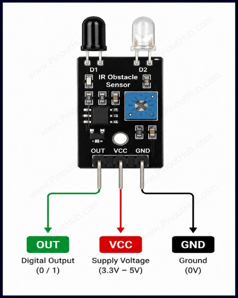
3-pin header pinout
| Pin | Name | Type | Description |
|---|---|---|---|
| 1 | VCC | Power | Supply input — 3.3V to 5V |
| 2 | GND | Power | Ground |
| 3 | OUT | Output | Digital output |
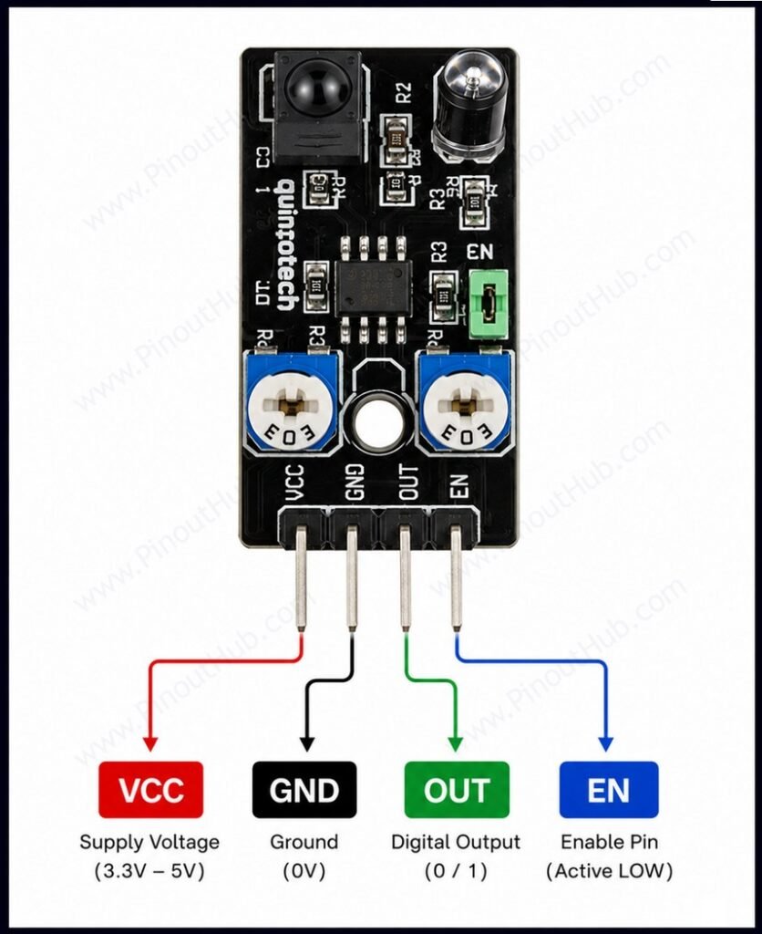
4-pin header pinout
| Pin | Name | Type | Description |
|---|---|---|---|
| 1 | VCC | Power | Supply input — 3.3V to 5V |
| 2 | GND | Power | Ground |
| 3 | D0 | Output | Digital output |
| 4 | A0 | Output | Analog output |
| OR | |||
| 4 | EN | Enable Pin |
Note: On 4-pin IR obstacle sensors, the fourth pin is not standardized. Depending on the module, it may be an Enable (EN) pin or an Analog Output (AO) pin
Digital output logic: The OUT / D0 pin is active LOW — it goes LOW when an obstacle is detected within the set range and returns HIGH when the path is clear. The output is directly compatible with any GPIO input pin on Arduino, ESP32, or Raspberry Pi without any additional components.
Analog output (4-pin variant only): The A0 pin provides a continuous voltage from the photodiode voltage divider, rising as a detected object moves closer and reflecting light more intensely. On a 10-bit ADC, this gives a relative distance indication — not a calibrated distance measurement in centimetres — and is useful for applications requiring graduated proximity response rather than a simple threshold trigger.
Enable Output(4-pin variant only): The EN (Enable) pin is used to turn the IR sensor module on or off without disconnecting its power supply.
Module construction
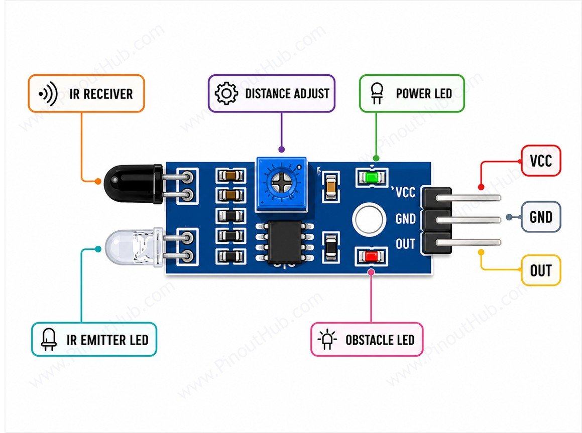
IR Transmitter LED An infrared LED, typically emitting at approximately 850nm, mounted on the front face of the PCB. Driven continuously through a current-limiting resistor from VCC. Emits an invisible cone of IR light in the forward direction.
IR Receiver Photodiode An infrared-sensitive photodiode positioned alongside the transmitter on the front face of the PCB. Sensitive to the same wavelength as the transmitter. Produces a small current proportional to the intensity of received IR light, which is converted to a voltage by a bias resistor.
LM393 Dual Comparator IC One comparator channel is used. Its non-inverting input receives the amplified photodiode signal; its inverting input is connected to the wiper of the potentiometer. When the photodiode signal exceeds the reference, the open-collector output pulls OUT LOW.
Sensitivity Potentiometer A small trimmer potentiometer that sets the reference voltage on the inverting input of the LM393, defining the signal threshold at which OUT switches. Adjusting it changes the effective detection distance between 2cm and 30cm.
Power Indicator LED Illuminates whenever VCC is applied to the module. Serves only as a power-on indicator.
Obstacle Indicator LED Connected to the OUT line. Illuminates when OUT goes LOW, providing a visible confirmation that an obstacle has been detected within range.
Specifications
| Parameter | Value |
|---|---|
| Supply Voltage | 3.3V – 5V DC |
| Operating Current | 20mA |
| Output Type | Digital, active LOW |
| Output Logic (obstacle) | LOW |
| Output Logic (clear) | HIGH |
| Detection Range | 2 – 30cm (adjustable) |
| Detection Angle | 35° |
| IR Transmitter Wavelength | ~850nm |
| Comparator IC | LM393 |
| Power Indicator LED | Yes |
| Obstacle Indicator LED | Yes |
| PCB Size | 31 × 14mm (typical) |
| Compatible Boards | Arduino, ESP32, Raspberry Pi |
Helpful Resources
- Download the datasheet: here
- IR Obstacle Sensor with Arduino
- IR Obstacle Sensor with ESP32
- IR Obstacle Sensor with Raspberry Pi