The single channel relay module is an electromechanical switching module relay that allows a microcontroller to switch high-voltage or high-current AC and DC loads using a standard 3.3V or 5V logic signal.
By combining the relay with a driver transistor, flyback protection diode, optocoupler isolation, and status LED on a single PCB, it provides a complete, safe, and ready-to-use interface between a microcontroller GPIO pin and mains or high-power circuits.
Pinout
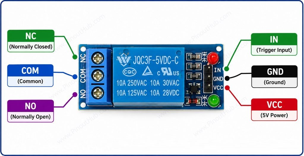
The 1-channel relay module has two separate connection areas — a 3-pin control header for the microcontroller and a 3-terminal screw block for the switched load.
3-pin control header
| Pin | Name | Type | Description |
|---|---|---|---|
| 1 | VCC | Power | Coil supply — connect to 5V DC; powers the relay coil via the driver transistor |
| 2 | GND | Power | Ground — connect to microcontroller GND; must share common ground with control circuit |
| 3 | IN | Input | Relay trigger input — active LOW on most modules: pull LOW to energize relay, HIGH to de-energize |
3-terminal output screw block
| Terminal | Name | Description |
|---|---|---|
| 1 | NO | Normally Open — open circuit when relay is de-energized; connects to COM when relay is energized |
| 2 | COM | Common — the switched terminal; connect the load supply wire here |
| 3 | NC | Normally Closed — connected to COM when relay is de-energized; opens when relay is energized |
Contact wiring for switching a load ON when triggered: Connect the load supply positive to COM and one terminal of the load to NO. When the relay energizes, COM connects to NO, completing the load circuit. When de-energized, the circuit breaks and the load turns off.
Contact wiring for switching a load OFF when triggered: Connect the load supply positive to COM and one terminal of the load to NC. The load runs continuously while the relay is de-energized. When the relay energizes, COM disconnects from NC, breaking the load circuit.
Common ground requirement: The GND pin of the control header must share a common ground with the microcontroller. Without a shared ground, the IN signal has no reference and the trigger will be unreliable or non-functional.
3.3V compatibility: Most relay modules are designed for 5V coil operation. When controlled from a 3.3V microcontroller such as the ESP32, the IN pin signal at 3.3V is generally sufficient to drive the optocoupler and transistor base on active LOW modules. However, the VCC pin must still be connected to 5V to properly energize the relay coil — the 3.3V supply alone cannot provide sufficient coil current.
Module Construction
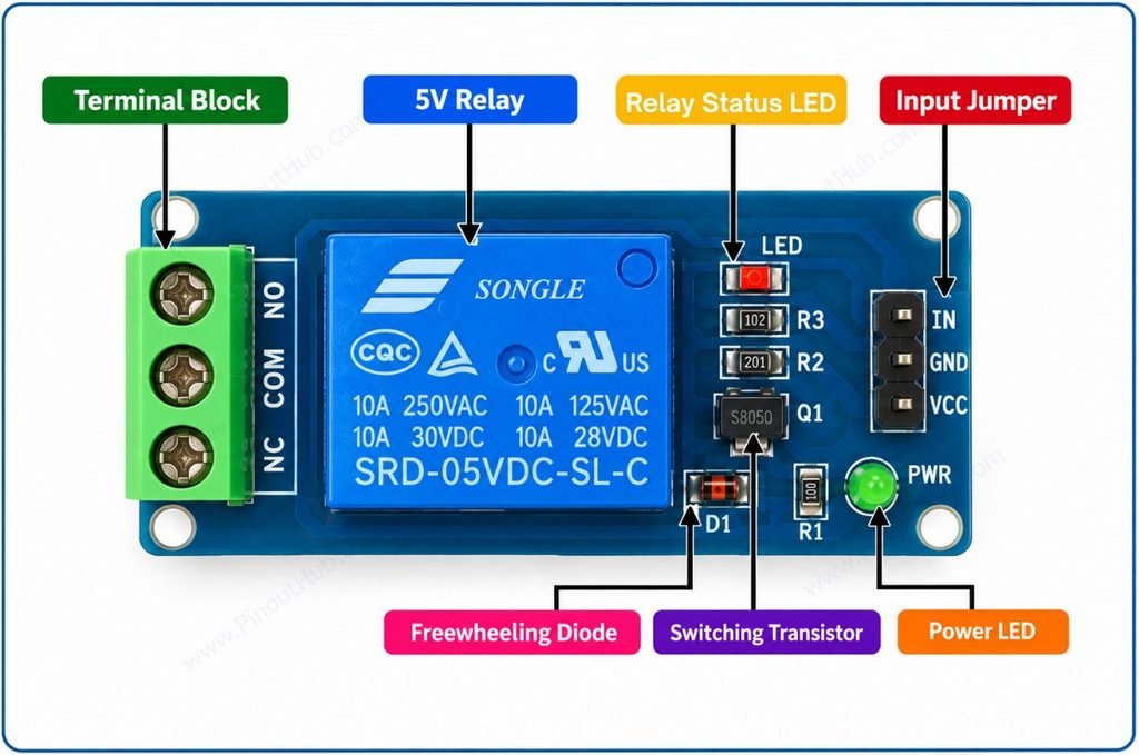
The 1-channel relay module consists of the following components:
5V Relay The Songle SPDT electromechanical relay at the center of the board. Contains the coil, armature, frame, and switching contacts — all sealed inside the blue housing. The coil operates at 5V DC with a resistance of approximately 70Ω, drawing ~71mA when energized.
Terminal Block A 3-pin green screw terminal block on the left edge of the board exposing the three relay contact terminals — NC (Normally Closed), COM (Common), and NO (Normally Open) — for connecting the switched load circuit.
Input Jumper A 3-pin 2.54mm pitch header on the right edge of the board labelled IN, GND, and VCC. Connects the module to the microcontroller — IN receives the trigger signal, GND connects to common ground, and VCC supplies 5V to the relay coil circuit.
Switching Transistor An NPN transistor that amplifies the low-current IN control signal into the ~71mA coil drive current required by the relay. Its base is driven through resistor R2; its collector connects to the relay coil through D1; its emitter connects to GND.
Freewheeling Diode (D1) A protection diode connected in reverse-bias across the relay coil. Clamps the back-EMF voltage spike generated when the coil is de-energized, preventing the spike from breaking down the switching transistor Q1.
Relay Status LED A red LED labelled LED on the board silkscreen. Illuminates when the relay is energized, providing visual confirmation that the relay contacts have switched. Driven through current-limiting resistor R3.
Power LED A green LED labelled PWR on the board silkscreen. Illuminates whenever VCC is applied to the input header, confirming the module is powered regardless of relay state. Driven through current-limiting resistor R1.
Resistors (R1, R2, R3) Three SMD resistors on the board. R1 limits current through the power indicator LED. R2 limits base current into the switching transistor Q1 from the IN pin. R3 limits current through the relay status LED.