The BTS7960 motor driver module is a high-current bidirectional DC motor driver built around two Infineon BTS7960B half-bridge ICs configured as a complete full H-bridge.
By combining a p-channel high-side MOSFET and an n-channel low-side MOSFET with an integrated driver IC in each package, it delivers up to 43A peak output current with built-in protection against overtemperature, overvoltage, undervoltage, overcurrent, and short circuit — all controllable from a microcontroller using standard TTL logic signals.
Pinout
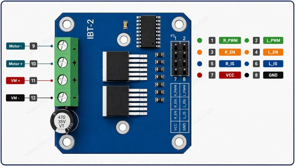
The BTS7960 module exposes all connections through two groups of screw terminals for power and motor connections, and an 8-pin signal header for microcontroller interface.
8-pin signal header
| Pin | Name | Type | Description |
|---|---|---|---|
| 1 | RPWM | Input | Right (forward) PWM input — controls speed in the forward direction; duty cycle sets motor speed |
| 2 | LPWM | Input | Left (reverse) PWM input — controls speed in the reverse direction; duty cycle sets motor speed |
| 3 | R_EN | Input | Right half-bridge enable — active HIGH; pull HIGH to enable forward H-bridge |
| 4 | L_EN | Input | Left half-bridge enable — active HIGH; pull HIGH to enable reverse H-bridge |
| 5 | R_IS | Output | Right half-bridge current sense — analog output proportional to forward current |
| 6 | L_IS | Output | Left half-bridge current sense — analog output proportional to reverse current |
| 7 | VCC | Power | 5V logic supply output — regulated from motor supply; can power microcontroller |
| 8 | GND | Power | Ground |
Power and motor screw terminals
| Terminal | Name | Description |
|---|---|---|
| 9 | Motor − | Motor output − |
| 10 | Motor + | Motor output + |
| 11 | VM + | Motor supply positive |
| 12 | VM − | Motor supply negative |
PWM and EN pin usage: To drive the motor forward, pull R_EN HIGH and send a PWM signal to RPWM while keeping LPWM LOW. To drive in reverse, pull L_EN HIGH and send a PWM signal to LPWM while keeping RPWM LOW. To brake, pull both RPWM and LPWM LOW simultaneously. Both enable pins must be HIGH for their respective half-bridge to operate — floating EN pins will disable that half-bridge.
VCC pin: The module includes an onboard 5V regulator that generates logic supply from the motor supply voltage. This 5V output is available on the VCC pin and can supply up to approximately 50mA to power a small microcontroller such as an Arduino Nano directly — eliminating the need for a separate 5V supply in small installations.
IS pins: The R_IS and L_IS current sense outputs provide an analog voltage proportional to the motor current in each half-bridge. Connect to a microcontroller ADC pin to implement software overcurrent protection or current monitoring. The IS output current is approximately 1/8500 of the actual motor current — with a series resistor to GND on the IS pin, this produces a measurable voltage.
Module construction
2 × BTS7960B ICs Two Infineon BTS7960B NovalithIC half-bridge packages, each in a TO-263-7 surface-mount package with an exposed thermal pad. One IC forms the right (forward) half-bridge; the other forms the left (reverse) half-bridge. Together they form a complete full H-bridge rated at 43A peak.
Aluminium Heatsink A large aluminium heatsink bonded to the thermal pads of both BTS7960B ICs. Essential for sustained high-current operation — at 25A continuous, the 16mΩ path resistance dissipates approximately 10W per IC (P = I² × R = 25² × 0.016), which must be conducted away from the junction to maintain temperature below the 150°C shutdown threshold.
5V Onboard Regulator Generates the 5V logic supply from the motor supply rail. Powers the internal driver ICs and the VCC output pin. Accepts any motor supply voltage within the 6–27V range.
Current Sense Resistors Small resistors on the R_IS and L_IS sense lines that convert the IS output current (1/8500 of motor current) into a measurable voltage for ADC sampling on the microcontroller.
Power Screw Terminals Heavy-duty screw terminals rated for the full peak current. Motor-side terminals (M+ / M−) and power-side terminals (B+ / B−) are physically separated on opposite ends of the board.
Signal Header An 8-pin 2.54mm pitch header exposing RPWM, LPWM, R_EN, L_EN, R_IS, L_IS, VCC, and GND for direct connection to microcontroller GPIO, PWM, and ADC pins.
Specifications
| Parameter | Value |
|---|---|
| Supply | |
| Motor Supply Voltage | 6V – 27V DC |
| Onboard Logic Regulator | 5V output |
| Output | |
| Continuous Output Current | 25A (with adequate heatsinking) |
| Peak Output Current | 43A |
| Path Resistance (RDSon) | 16mΩ typical at 25°C |
| PWM Frequency | Up to 25kHz |
| Control | |
| Logic Input Levels | 3.3V / 5V TTL |
| Forward Control | RPWM + R_EN |
| Reverse Control | LPWM + L_EN |
| Current Sense | R_IS / L_IS (1/8500 of motor current) |
| Protection | |
| Overtemperature Shutdown | Yes (150°C junction) |
| Overvoltage Protection | Yes |
| Undervoltage Lockout | Yes |
| Overcurrent / Short Circuit | Yes (switched-mode current limitation) |
| Dead Time Generation | Yes (internal, automatic) |
| General | |
| Operating Temperature (junction) | −40°C to +150°C |
| IC Package | 2 × TO-263-7 (D2PAK) |
| RoHS | Compliant |
Helpful resources
- Download the datasheet: here
- BTS7960 with Arduino
- BTS7960 with ESP32
- BTS7960 with Raspberry Pi