The 4-channel relay module is an electromechanical switching module that allows a microcontroller to independently switch four high-voltage or high-current AC and DC loads using standard 3.3V or 5V logic signals.
By combining four relays with driver transistors, flyback protection diodes, optocoupler isolation, and status LEDs on a single PCB, it provides a complete, safe, and ready-to-use interface between microcontroller GPIO pins and mains or high-power circuits.
Pinout
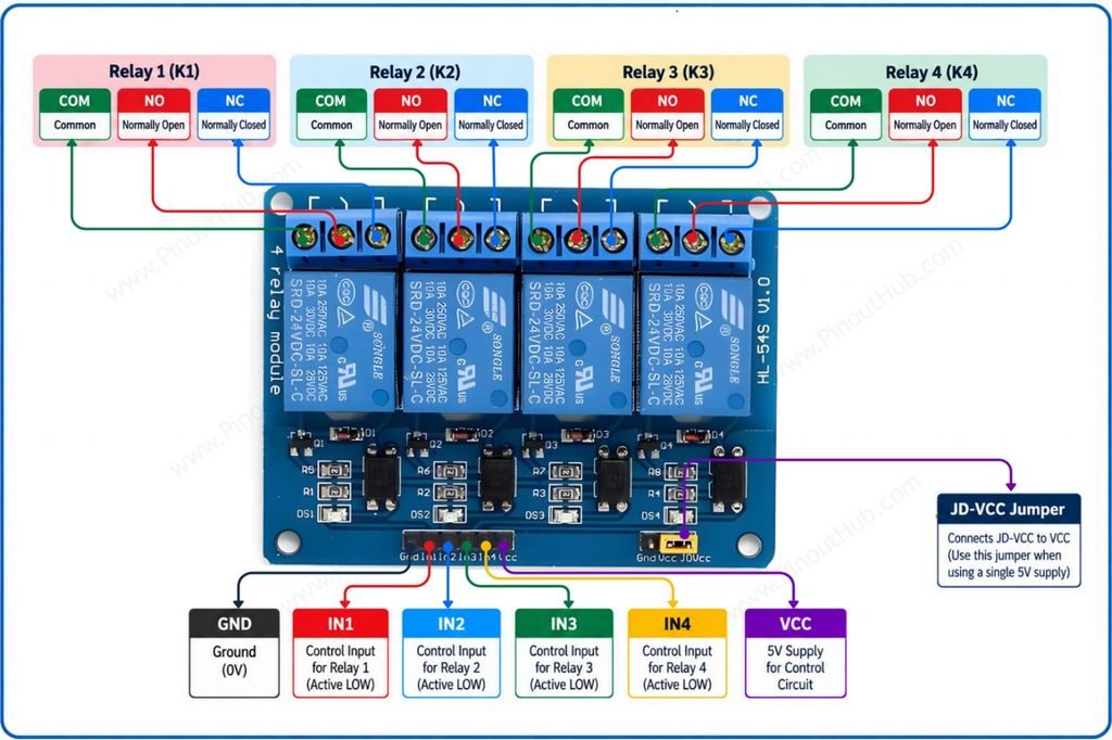
The 4-channel relay module has two separate connection areas — a 6-pin control header for the microcontroller and four 3-terminal screw blocks for the switched loads.
6-pin control header
| Pin | Name | Type | Description |
|---|---|---|---|
| 1 | VCC | Power | Coil supply — connect to 5V DC; powers the relay coils through the driver transistors |
| 2 | GND | Power | Ground — connect to microcontroller GND; provides the reference for the control circuit |
| 3 | IN1 | Input | Relay 1 trigger input — active LOW on most modules: pull LOW to energize relay 1, HIGH to de-energize |
| 4 | IN2 | Input | Relay 2 trigger input — active LOW on most modules: pull LOW to energize relay 2, HIGH to de-energize |
| 5 | IN3 | Input | Relay 3 trigger input — active LOW on most modules: pull LOW to energize relay 3, HIGH to de-energize |
| 6 | IN4 | Input | Relay 4 trigger input — active LOW on most modules: pull LOW to energize relay 4, HIGH to de-energize |
12-terminal output screw blocks
| Terminal | Name | Description |
|---|---|---|
| 1 | NO1 | Normally Open — open circuit when relay 1 is de-energized; connects to COM1 when relay 1 is energized |
| 2 | COM1 | Common — the switched terminal for relay 1; connect the load supply wire here |
| 3 | NC1 | Normally Closed — connected to COM1 when relay 1 is de-energized; opens when relay 1 is energized |
| 4 | NO2 | Normally Open — open circuit when relay 2 is de-energized; connects to COM2 when relay 2 is energized |
| 5 | COM2 | Common — the switched terminal for relay 2; connect the load supply wire here |
| 6 | NC2 | Normally Closed — connected to COM2 when relay 2 is de-energized; opens when relay 2 is energized |
| 7 | NO3 | Normally Open — open circuit when relay 3 is de-energized; connects to COM3 when relay 3 is energized |
| 8 | COM3 | Common — the switched terminal for relay 3; connect the load supply wire here |
| 9 | NC3 | Normally Closed — connected to COM3 when relay 3 is de-energized; opens when relay 3 is energized |
| 10 | NO4 | Normally Open — open circuit when relay 4 is de-energized; connects to COM4 when relay 4 is energized |
| 11 | COM4 | Common — the switched terminal for relay 4; connect the load supply wire here |
| 12 | NC4 | Normally Closed — connected to COM4 when relay 4 is de-energized; opens when relay 4 is energized |
Contact wiring for switching a load ON when triggered: Connect the load supply positive to the appropriate COM terminal and one terminal of the load to the corresponding NO terminal. When the relay energizes, COM connects to NO, completing the load circuit. When de-energized, the circuit breaks and the load turns off. Each relay channel can control a separate load independently.
Contact wiring for switching a load OFF when triggered: Connect the load supply positive to the appropriate COM terminal and one terminal of the load to the corresponding NC terminal. The load runs continuously while the relay is de-energized. When the relay energizes, COM disconnects from NC, breaking the load circuit.
Common ground requirement: The GND pin of the control header must share a common ground with the microcontroller. Without a shared ground, the IN1, IN2, IN3, and IN4 signals have no reference and the triggers will be unreliable or non-functional.
3.3V compatibility: Most relay modules are designed for 5V coil operation. When controlled from a 3.3V microcontroller such as the ESP32, the input signals at 3.3V are generally sufficient to drive the optocouplers and transistor driver circuits on compatible modules. However, the VCC pin must still be connected to 5V to properly energize the relay coils — a 3.3V supply alone cannot provide sufficient voltage for the 5V relay coils.