The TMC2209 is an ultra-silent microstepping motor driver module built around the Trinamic TMC2209 IC that drives two-phase bipolar stepper motors using the standard STEP/DIR interface while delivering near-silent operation through advanced chopper technology.
It can handle a maximum output of 28 V and ±2 A, supporting bipolar stepper motors in 1 to 1/256 step modes. This IC utilizes StealthChop2 technology to ensure quiet motor performance.
Pinout
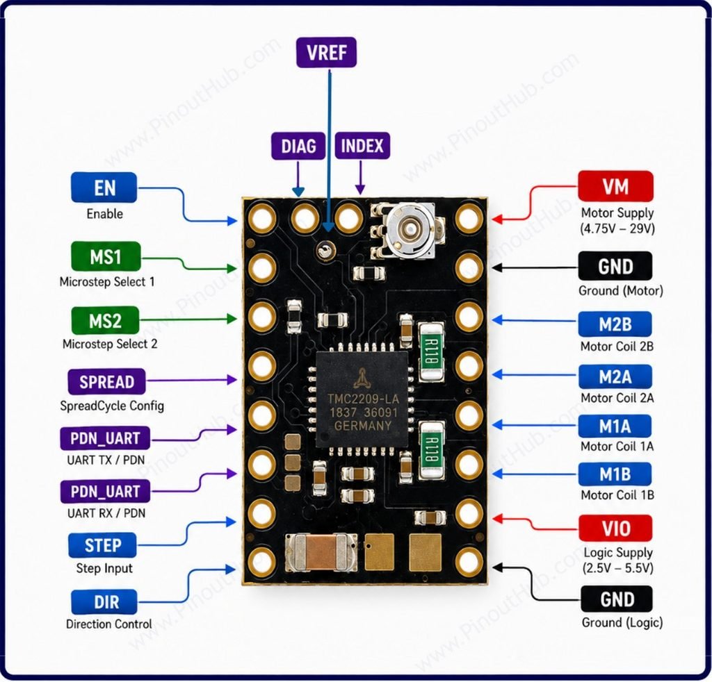
| Pin | Name | Description |
|---|---|---|
| 1 | EN | Enable input; sets driver enable/disable state |
| 2 | MS1 | Microstep select input 1 |
| 3 | MS2 | Microstep select input 2 |
| 4 | SPREAD | SpreadCycle configuration input |
| 5 | PDN_UART | UART TX / power-down-not pin |
| 6 | PDN_UART | UART RX / power-down-not pin |
| 7 | STEP | Step pulse input |
| 8 | DIR | Direction control input |
| 9 | VREF | Reference voltage input for current setting |
| 10 | DIAG | Diagnostic output (stall/error indication) |
| 11 | INDEX | Index pulse output |
| 12 | VM | Motor power supply input (4.75V–29V) |
| 13 | GND | Ground (motor side) |
| 14 | M2B | Motor coil 2B output |
| 15 | M2A | Motor coil 2A output |
| 16 | M1A | Motor coil 1A output |
| 17 | M1B | Motor coil 1B output |
| 18 | VIO | Logic supply voltage input (2.5V–5.5V) |
| 19 | GND | Ground (logic side) |
PDN_UART appears twice on the board — one pad routes UART TX, the other UART RX, with the pin also serving as the power-down-not control when UART mode is disabled.
Module construction
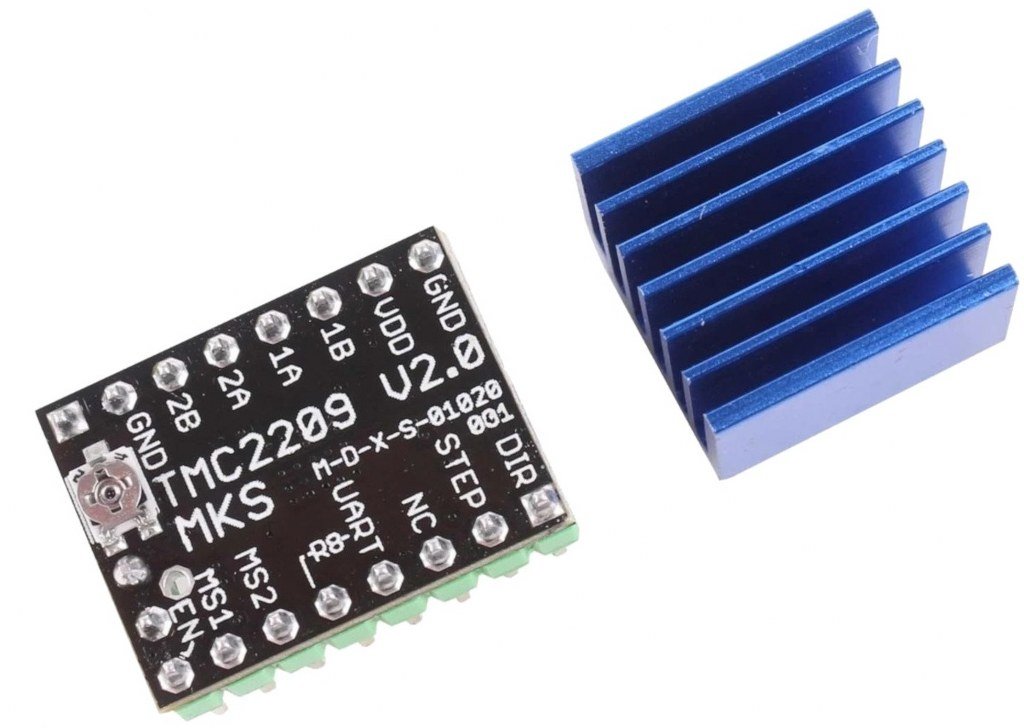
TMC2209 IC A 28-pad QFN package with an exposed thermal pad on the underside that conducts heat directly to the PCB ground plane. Contains two N-channel MOSFET H-bridges (170mΩ RDSon each), StealthChop2 chopper, SpreadCycle chopper, StallGuard4 load sensor, MicroPlyer interpolator, CoolStep current controller, 12.5MHz internal oscillator, single-wire UART interface, and full protection circuitry.
Current Sense Resistors Two precision resistors on the low-side of each H-bridge used by the IC to monitor coil current. The current limit is set via the UART IRUN register or by the onboard potentiometer on modules that include one. Current limit formula: IRMS = (VREF × 0.707) ÷ (2.5 × RS).
Current Limiting Potentiometer Present on standalone module variants. Sets the VREF voltage which controls the maximum RMS coil current. On 3D printer mainboard socket variants (e.g. SilentStepStick), current is typically set via UART instead.
100µF Bulk Capacitor A large electrolytic capacitor across VM and GND that absorbs inductive voltage spikes from the motor coils. Essential — without it, spikes can exceed the 28V VM maximum and permanently damage the IC.
VIO / VM Decoupling Capacitors Small ceramic capacitors on both supply rails that filter high-frequency switching noise from the H-bridge switching transitions.
UART Resistor A 1kΩ series resistor on the PDN/UART pin on most modules, allowing the single-wire UART to be driven from a standard microcontroller UART TX pin without bus contention.
Specifications
| Parameter | Value |
|---|---|
| Supply | |
| Motor Supply Voltage (VM) | 4.75V – 28V DC |
| Logic Supply Voltage (VIO) | 3.0V – 5.25V |
| RDSon (HS + LS) | 170mΩ + 170mΩ typical at 25°C |
| Output | |
| Peak Output Current | 2.8A per coil |
| RMS Output Current | 2.0A per coil |
| Microstepping | |
| Hardware Step Modes | 1/8 / 1/16 / 1/32 / 1/64 |
| Interpolated (MicroPlyer) | Up to 1/256 |
| Control | |
| Control Interface | STEP / DIR |
| Configuration Interface | Single-wire UART (CRC-checked) |
| OTP Memory | Yes |
| Logic Input Levels | 3.3V / 5V TTL |
| ENABLE | Active LOW |
| Technology | |
| Silent Chopper | StealthChop2 |
| Dynamic Chopper | SpreadCycle |
| Sensorless Homing | StallGuard4 |
| Current Optimization | CoolStep (up to 75% saving) |
| Microstep Interpolation | MicroPlyer (to 256) |
| Protection | |
| Overcurrent Protection | Yes |
| Thermal Shutdown | Yes |
| Short to GND / Supply | Yes |
| Open Load Detection | Yes |
| Under-Voltage Lockout | Yes |
| General | |
| Operating Temperature | −40°C to +125°C |
| IC Package | 28-pad QFN with thermal pad |
| RoHS | Compliant |
Helpful resources
- Download the datasheet: here
- TMC2209 with Arduino
- TMC2209 with ESP32
- TMC2209 with Raspberry Pi