The Raspberry Pi Zero is one of the smallest and most affordable Raspberry Pi boards, built around the Broadcom BCM2835 processor running at 1 GHz with 512 MB RAM. This is the original version of the Raspberry Pi Zero and does not feature built-in Wi-Fi or Bluetooth connectivity.
Official Pinout
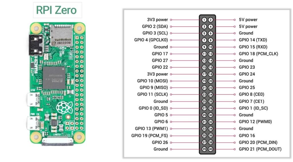
Power pins
The GPIO header includes both 3.3V and 5V power pins that can be used to power low-power external components.
3.3V Pins
- Pin 1
- Pin 17
These pins provide 3.3V output from the onboard voltage regulator and are typically used to power sensors and logic modules.
5V Pins
- Pin 2
- Pin 4
These pins are connected directly to the 5V power input rail of the board.
Ground pins
Ground pins provide the reference voltage for circuits connected to the Raspberry Pi.
The following pins are connected to ground:
6, 9, 14, 20, 25, 30, 34, 39
These pins complete electrical circuits when connecting external hardware.
I2C Pins
The I2C interface allows the Raspberry Pi to communicate with sensors and other peripherals using two wires.
| GPIO | Physical Pin | Function |
|---|---|---|
| GPIO2 | Pin 3 | SDA (Data) |
| GPIO3 | Pin 5 | SCL (Clock) |
I2C is commonly used with devices such as:
- OLED displays
- RTC modules
- environmental sensors
SPI Pins
The SPI interface supports high-speed communication with peripherals like displays and ADC modules.
| GPIO | Pin | Function |
|---|---|---|
| GPIO10 | 19 | MOSI |
| GPIO9 | 21 | MISO |
| GPIO11 | 23 | SCLK |
| GPIO8 | 24 | CE0 |
| GPIO7 | 26 | CE1 |
UART pins
The UART interface provides serial communication between the Raspberry Pi and other devices.
| GPIO | Pin | Function |
|---|---|---|
| GPIO14 | Pin 8 | TX |
| GPIO15 | Pin 10 | RX |
PWM pins
Pulse Width Modulation (PWM) allows control of devices such as LED brightness, motors, and servo motors.
PWM-capable pins include:
- GPIO12
- GPIO13
- GPIO18
- GPIO19
Specifications
| Feature | Specification |
|---|---|
| Processor | Broadcom BCM2835 |
| CPU Architecture | ARM1176JZF-S (ARMv6) |
| CPU Clock Speed | 1 GHz |
| GPU | Broadcom VideoCore IV |
| RAM | 512 MB LPDDR2 SDRAM |
| Wireless Connectivity | Not available |
| Bluetooth | Not available |
| Ethernet | Not available |
| USB Ports | 1 × USB 2.0 (OTG) |
| Power Input | Micro-USB power connector |
| Display Output | Mini HDMI |
| Camera Interface | CSI camera connector |
| GPIO Header | 40-pin GPIO (not pre-soldered) |
| Storage | microSD card slot |
| Composite Video | Available via test pads |
| Operating System | Raspberry Pi OS and other Linux distributions |
| Board Dimensions | 65 mm × 30 mm |
Important usage notes
Important usage notes
1. GPIO pins are not 5V tolerant
All GPIO pins on the Raspberry Pi Zero operate at 3.3V logic levels. Applying 5V directly to any GPIO pin can permanently damage the processor.
If you need to connect devices that operate at 5V logic, use a level shifter or voltage divider to safely step the voltage down.
2. Current limit
GPIO pins are intended for signal control rather than powering devices.
- Maximum current per GPIO pin: 16 mA
- Recommended current per pin: 8 mA or less
- Total current across all GPIO pins: about 50 mA
3. Boot configuration pins
Some GPIO pins are read during the boot process to determine certain system settings. Connecting external hardware to these pins may affect the startup behavior of the board. If the Raspberry Pi fails to boot correctly, check whether connected devices are interfering with these pins.
4. GPIO header may require soldering
The Raspberry Pi Zero is typically shipped with an unsoldered 40-pin GPIO header. To use jumper wires or attach expansion boards, the header may need to be soldered onto the board.
5. Verify pin orientation
Before making connections, always confirm the orientation of the GPIO header.
Pin 1 is the 3.3V pin located near the corner of the board, and the odd-numbered pins run along the outer row of the header. Double-checking the pinout diagram can help prevent wiring mistakes.
6. No WiFi or Bluetooth
Unlike the Raspberry Pi Zero W, the original Raspberry Pi Zero does not include built-in Wi-Fi or Bluetooth.
If network connectivity is required, you must use an external device such as:
- USB Wi-Fi adapter
- USB Ethernet adapter
- USB hub with network interface
This is important to consider when designing IoT or remote-control projects.
7. Micro-USB ports have different functions
The board includes two micro-USB ports, but they serve different purposes.
- USB (Data) – Used for connecting USB peripherals via OTG
- PWR IN – Used only for powering the board
Connecting power to the wrong port will not damage the board, but peripherals will not work correctly.
Useful resources
1. Getting started with Pi Zero(setup)
2. This one is a really helpful documentation on Pi Zero by Adafruit