The ESP32-S3 DevKitC-1 stands out from earlier ESP32 boards with its native USB support and enhanced AI/vector instructions, making it suitable for both IoT and edge-processing applications. Built around the Xtensa LX7 dual-core processor, it also offers a wide range of GPIO functions, including touch sensing and analog input.
This guide provides a detailed look at the ESP32-S3 DevKitC-1 pinout, helping you understand how each pin can be used in real-world applications.
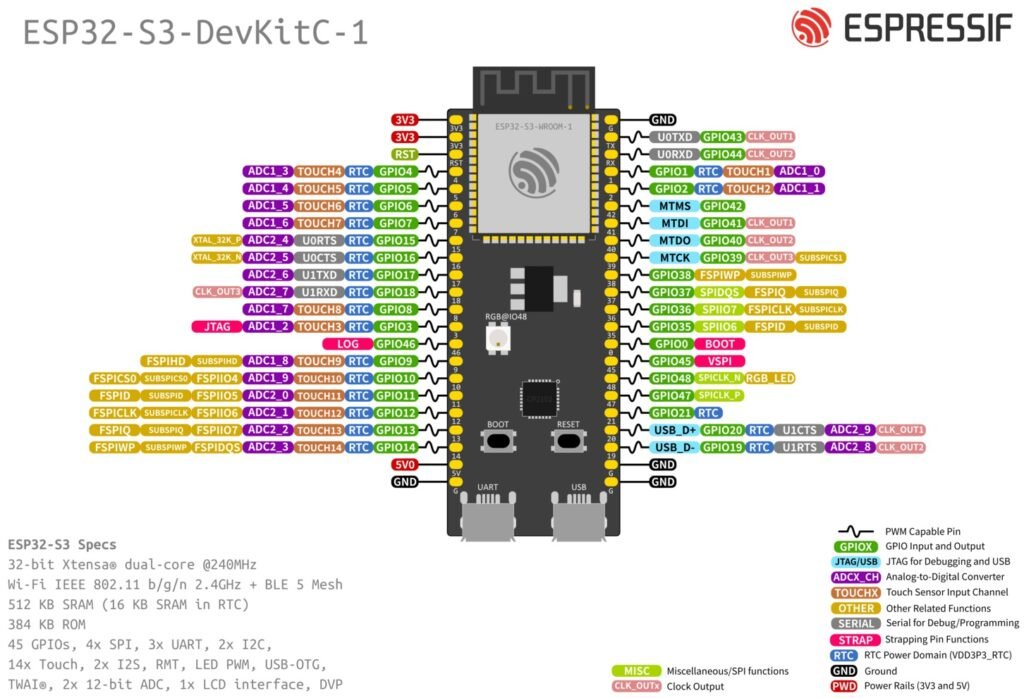
ESP32-S3 DevKitC-1 pinout
The GPIO system of the ESP32-S3 DevKitC-1 includes up to 45 GPIOs, with support for 12-bit ADC channels, multiple PWM outputs, capacitive touch inputs, and hardware interfaces like SPI, I2C, and UART. Thanks to the internal pin matrix, most peripheral functions can be routed to different pins.
Power Pins
The board provides multiple power input and output options.
- 3.3V Pin – 2 pins
- 5V – 1 pin(Outputs 5V)
- GND Pins – 4 pins
Board operates at 3.3V logic levels.
ADC (Analog Input) Pins
The ESP32-S3 provides two ADC units (ADC1 and ADC2) with 12-bit resolution, visible in the diagram as ADC1_x and ADC2_x channels.
AD1_x pins
- GPIO1 → ADC1_0
- GPIO2 → ADC1_1
- GPIO4 → ADC1_3
- GPIO5 → ADC1_4
- GPIO6 → ADC1_5
- GPIO7 → ADC1_6
- GPIO8 → ADC1_7
- GPIO9 → ADC1_8
- GPIO10 → ADC1_9
AD2_x pins:
- GPIO11 → ADC2_0
- GPIO12 → ADC2_1
- GPIO13 → ADC2_2
- GPIO14 → ADC2_3
- GPIO15 → ADC2_4
- GPIO16 → ADC2_5
- GPIO17 → ADC2_6
- GPIO18 → ADC2_7
- GPIO19 → ADC2_8
- GPIO20 → ADC2_9
ADC2 is shared with Wi-Fi, so readings may be unreliable when Wi-Fi is active.
Touch Sensor Pins
The ESP32-S3 includes capacitive touch sensing on multiple GPIOs, labeled as TOUCHx in the diagram.
Examples:
- GPIO1 → TOUCH1
- GPIO2 → TOUCH2
- GPIO3 → TOUCH3
- GPIO4 → TOUCH4
- GPIO5 → TOUCH5
- GPIO6 → TOUCH6
- GPIO7 → TOUCH7
- GPIO8 → TOUCH8
- GPIO9 → TOUCH9
- GPIO10 → TOUCH10
- GPIO11 → TOUCH11
- GPIO12 → TOUCH12
- GPIO13 → TOUCH13
- GPIO14 → TOUCH14
These pins can detect touch without physical contact and are useful for:
- Touch buttons
- Control panels
- IoT interfaces
PWM pins
The ESP32-S3 uses the LEDC (LED Controller) peripheral to generate PWM signals. Unlike traditional microcontrollers, PWM is not limited to specific pins.
- Up to 8 PWM channels
- Configurable frequency and resolution
- Works on most GPIO pins
- Suitable for:
- LED dimming
- Servo control
- Motor speed control
Pins to avoid for PWM
Input-only pin
- GPIO46 (Left Pin 13) → Cannot generate PWM
Reserved pins
- GPIO35, GPIO36, GPIO37 (Right Pins 12–14) → Used for flash/PSRAM
Boot/strapping pins
- GPIO0 (Right Pin 15)
- GPIO45 (Right Pin 16)
SPI Pins (flash & general SPI)
The ESP32-S3 includes:
- SPI0 / SPI1 → Internal (Flash & PSRAM)
- SPI2 (FSPI) → General purpose
- SPI3 (HSPI) → General purpose
| Controller | Usage | Availability |
|---|---|---|
| SPI0 | Internal flash/PSRAM | Not usable |
| SPI1 | Internal flash/PSRAM | Not usable |
| SPI2 | General-purpose SPI | Usable |
| SPI3 | General-purpose SPI | Usable |
While the ESP32-S3 supports flexible pin mapping via the GPIO matrix, the following pins are commonly used as a default configuration(SPI2):
| Signal | GPIO |
|---|---|
| MOSI | GPIO11 |
| MISO | GPIO13 |
| SCLK | GPIO12 |
| CS | GPIO10 |
Flash SPI (Internal – Avoid Using)
Pins labeled with FSPI / SUBSPI are typically connected to internal flash memory:
- GPIO35 → FSPID
- GPIO36 → FSPICLK
- GPIO37 → FSPIDQS
- GPIO38 → FSPIWP
- GPIO39 → FSPICS
These pins should generally not be used for external components, as they are internally used by the ESP32.
UART Pins
The ESP32-S3 supports multiple UART interfaces.
Common pins:
- GPIO43 → U0TXD (default TX)
- GPIO44 → U0RXD (default RX)
Additional UART signals are multiplexed across other pins:
- GPIO17 → U1TXD
- GPIO18 → U1RXD
- GPIO15 → U0RTS
- GPIO16 → U0CTS
USB Interface Pins
One of the key features of the ESP32-S3 is native USB support.
- GPIO20 → USB D+
- GPIO19 → USB D−
These pins enable:
- USB serial communication (CDC)
- HID devices (keyboard, mouse)
- Direct PC connectivity without UART bridge
JTAG (Debugging) Pins
The ESP32-S3 includes built-in debugging support via JTAG:
- GPIO39 → MTCK
- GPIO40 → MTDO
- GPIO41 → MTDI
- GPIO42 → MTMS
These pins are used for:
- Hardware debugging
- Advanced development workflows
Strapping Pins (Boot Configuration)
Some pins affect the boot mode of the ESP32-S3 and must be used carefully:
- GPIO0 → Boot mode selection
- GPIO45 → Strapping pin
- GPIO46 → Strapping / input-only
Incorrect connections on these pins can prevent the board from booting properly.
Input-only pin
- GPIO46 is input-only and cannot be used as an output pin.
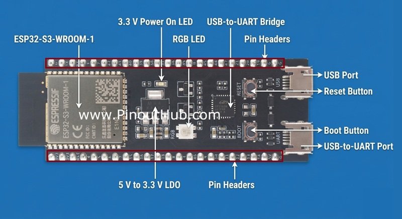
RGB LED pin
- GPIO48 is connected to the onboard RGB LED, which can be used for status indication or user feedback.
ESP32-S3 DevKitC-1 Specifications
Core Specifications
| Feature | Specification |
|---|---|
| Microcontroller | ESP32-S3 |
| CPU | Dual-core Xtensa LX7 |
| Clock Speed | Up to 240 MHz |
| AI Acceleration | Vector instructions for AI/ML |
| SRAM | 512 KB |
| External RAM (PSRAM) | Up to 8 MB (module dependent) |
| Flash Memory | Up to 16 MB (module dependent) |
Connectivity
| Feature | Specification |
|---|---|
| Wi-Fi | 2.4 GHz Wi-Fi (802.11 b/g/n) |
| Bluetooth | Bluetooth 5 (BLE) |
| USB | Native USB OTG (Type-C) |
GPIO & peripherals
| Feature | Specification |
|---|---|
| GPIO Pins | Up to 45 (varies by board exposure) |
| ADC | 12-bit, up to 20 channels |
| PWM | Up to 8 channels (LEDC) |
| UART | 3 UART interfaces |
| SPI | 2 general-purpose SPI (SPI2, SPI3) |
| I2C | Multiple (flexible pins) |
| I2S | Yes (audio interface) |
| Touch Sensors | 14 capacitive touch pins |
Power
| Feature | Specification |
|---|---|
| Operating Voltage | 3.3V |
| Input Voltage | 5V via USB or VIN |
| Power Regulation | Onboard LDO regulator |
Board features
| Feature | Specification |
|---|---|
| USB Interface | USB Type-C |
| Boot Button | Yes |
| Reset Button | Yes |
| Onboard LED | RGB LED (GPIO48) |
| USB-to-Serial | May vary (some use native USB) |
Important usage notes
- Avoid GPIO35–37 (Right Pins 12–14) → Reserved for flash/PSRAM
- Avoid GPIO0 (Right Pin 15) → Boot pin
- Avoid GPIO45 (Right Pin 16) → Strapping pin
- GPIO46 (Left Pin 13) is input-only (no output/PWM)
- Do not apply 5V to GPIOs (3.3V logic only)
- Avoid using GPIO43 (TX) & GPIO44 (RX) if using Serial/USB
- Do not pull GPIO0, 45, 46 HIGH/LOW during boot
- Use recommended pins: GPIO4–18, GPIO47–48
- Avoid high current from 3.3V pin (Left Pin 1)
- Prefer default pins for UART, SPI, I2C for stability
Helpful resources
- Watch this video tutorial on getting started with the ESP32S3 Devkit v1
- Official documentation is here