The MX1508 is a compact dual H-bridge motor driver module built around the MX1508 IC that controls the speed and direction of two DC motors or one bipolar stepper motor simultaneously.
By integrating two full H-bridge circuits using P-channel and N-channel power MOSFETs with built-in thermal protection and a floating-input protection circuit, it delivers efficient bidirectional motor control in an ultra-compact footprint suitable for battery-powered applications.
Pinout
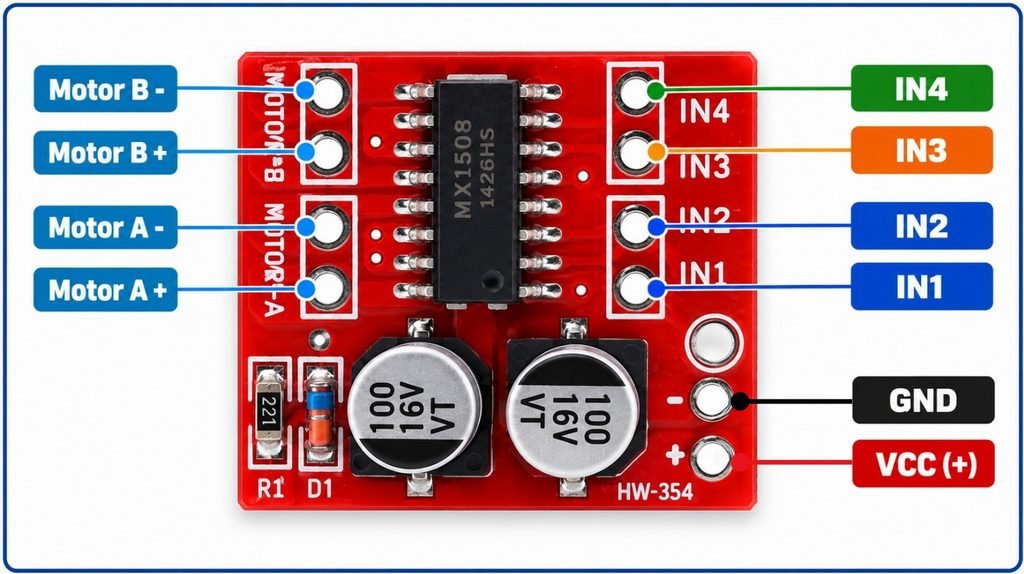
The MX1508 module exposes eight pins through two rows of through-hole pads or headers — a power and motor output row on one side, and a control input row on the other. All pins are clearly labelled on the module silkscreen.
Power and motor output pins
| Pin | Name | Type | Description |
|---|---|---|---|
| 1 | + | Power | Motor supply positive — connect to 2V to 10V DC |
| 2 | − | Power | Motor supply ground |
| 3 | MA1 | Output | Motor A output terminal 1 — connect to one terminal of Motor A |
| 4 | MA2 | Output | Motor A output terminal 2 — connect to other terminal of Motor A |
| 5 | MB1 | Output | Motor B output terminal 1 — connect to one terminal of Motor B |
| 6 | MB2 | Output | Motor B output terminal 2 — connect to other terminal of Motor B |
Control input pins
| Pin | Name | Type | Description |
|---|---|---|---|
| 1 | IN1 | Input | Direction control input 1 for Motor A — connect to microcontroller GPIO or PWM pin |
| 2 | IN2 | Input | Direction control input 2 for Motor A — connect to microcontroller GPIO or PWM pin |
| 3 | IN3 | Input | Direction control input 1 for Motor B — connect to microcontroller GPIO or PWM pin |
| 4 | IN4 | Input | Direction control input 2 for Motor B — connect to microcontroller GPIO or PWM pin |
PWM speed control: To control motor speed, drive one IN pin with a PWM signal and hold the other LOW (for one direction) or drive both with complementary PWM signals. The duty cycle of the PWM signal directly sets the average voltage delivered to the motor and therefore its speed. The MX1508 input accepts PWM signals from both 3.3V and 5V microcontrollers within the 1.8V–7V signal input range.
Floating input behavior: When all IN pins are left unconnected, the built-in common conduction circuit holds the motor outputs in a safe off state, preventing the motor from running uncontrollably due to undefined input logic levels.
Specifications
| Parameter | Value |
|---|---|
| Supply | |
| Motor Supply Voltage | 2V – 10V DC |
| Signal Input Voltage | 1.8V – 7V |
| Standby Current | < 0.1µA |
| Output | |
| Continuous Output Current | 1.5A per channel |
| Peak Output Current | 2.5A per channel |
| Control | |
| PWM Speed Control | Yes |
| Motor Channels | 2 DC motors / 1 bipolar stepper |
| Protection | |
| Thermal Shutdown (TSD) | Yes (auto-recovery with hysteresis) |
| Floating Input Protection | Yes |
| Physical | |
| Dimensions | 24.7 × 21 × 5mm |
| Mounting Hole Diameter | 2mm |
| RoHS | Compliant |
Helpful resources
- Download the datasheet: here
- MX1508 with Arduino