The TB6600 is a high-current professional-grade microstepping motor driver module built around the Toshiba TB6600HG IC that drives 2-phase and 4-phase bipolar stepper motors using a standard STEP/DIR pulse interface. By combining optocoupler-isolated signal inputs, a wide motor supply voltage range, DIP-switch configurable microstepping and current settings, and a rugged aluminium enclosure, it delivers reliable and precise stepper motor control suitable for both maker and light industrial applications.
Pinout
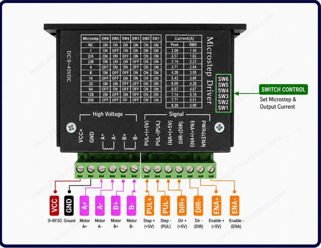
The common TB6600-style stepper driver has separate control signal, motor output, and power supply terminals. Exact labeling can vary slightly between module versions, but the functions are generally the same.
| Pin / Terminal | Label | Function |
|---|---|---|
| Enable + | ENA+ | Positive enable signal input |
| Enable − | ENA− | Negative enable signal input |
| Direction + | DIR+ | Positive direction-control input |
| Direction − | DIR− | Negative direction-control input |
| Pulse + | PUL+ | Positive step/pulse input |
| Pulse − | PUL− | Negative step/pulse input |
| Motor Coil A+ | A+ | Positive terminal of motor coil A |
| Motor Coil A− | A− | Negative terminal of motor coil A |
| Motor Coil B+ | B+ | Positive terminal of motor coil B |
| Motor Coil B− | B− | Negative terminal of motor coil B |
| Power + | VCC | Positive DC motor power supply |
| Power − | GND | Negative DC power supply |
Note: TB6600 modules commonly use PUL for step/pulse, DIR for direction, and ENA for enable. The motor connects to A+/A− and B+/B−, while the driver supply connects to VCC/GND. Typical modules accept a DC supply in the roughly 9–42 V range, but the exact voltage and current limits depend on the specific driver version.
DIP Switch Configuration
Six onboard DIP switches configure microstepping resolution (SW1–SW3) and output current (SW4–SW6). Settings take effect immediately when switches are changed — no power cycle is required.
Microstepping selection (SW1 / SW2 / SW3)
| SW1 | SW2 | SW3 | Step Mode |
|---|---|---|---|
| ON | ON | ON | Full step |
| OFF | ON | ON | Half step (1/2) |
| ON | OFF | ON | Quarter step (1/4) |
| OFF | OFF | ON | Eighth step (1/8) |
| ON | ON | OFF | Sixteenth step (1/16) |
| OFF | ON | OFF | Thirty-second step (1/32) |
Current selection (SW4 / SW5 / SW6)
| SW4 | SW5 | SW6 | Current |
|---|---|---|---|
| ON | ON | ON | 0.5A |
| OFF | ON | ON | 1.0A |
| ON | OFF | ON | 1.5A |
| OFF | OFF | ON | 2.0A |
| ON | ON | OFF | 2.5A |
| OFF | ON | OFF | 2.8A |
| ON | OFF | OFF | 3.0A |
| OFF | OFF | OFF | 3.5A |
Set the current to match or slightly below the rated current of the stepper motor. Running the driver at a current higher than the motor’s rated value will overheat the motor windings without increasing useful torque.
Module Construction
TB6600HG IC The Toshiba TB6600HG single-chip bipolar microstepping driver IC. Contains two full N-channel MOSFET H-bridges, the internal microstepping indexer, fixed off-time PWM current regulator, and overcurrent and thermal protection circuitry.
Optocouplers High-speed optocouplers on the PUL, DIR, and ENA signal inputs provide complete galvanic isolation between the microcontroller signal ground and the motor power ground. Each optocoupler LED is driven by the external signal source through a series current-limiting resistor, requiring a 5V TTL signal for reliable switching.
6-Switch DIP Block Two groups of three switches — SW1–SW3 for microstepping and SW4–SW6 for current — allow field configuration without tools, software, or potentiometer adjustment. Settings are applied in hardware and take effect immediately.
Screw Terminal Blocks Heavy-duty screw terminals on both the signal side and motor/power side allow secure connection of wiring without soldering. Motor-side terminals are rated for the full 4A output current and accept wire gauges appropriate for high-current wiring.
Aluminium Enclosure A compact aluminium shell that encloses all PCB components and acts as a passive heatsink for the TB6600HG IC. Provides mechanical protection and EMI shielding in addition to thermal management.
Power and Operation Indicator LEDs Onboard LEDs indicate power-on status and active operation, providing at-a-glance confirmation that the driver is powered and receiving step pulses.
Specifications
| Parameter | Value |
|---|---|
| Supply | |
| Motor Supply Voltage | 9V – 42V DC |
| Output | |
| Continuous Output Current | 4.0A (DIP selectable) |
| Peak Output Current | 4.5A |
| Current Steps | 0.5 / 1.0 / 1.5 / 2.0 / 2.5 / 2.8 / 3.0 / 3.5A |
| Microstepping | |
| Step Modes | Full / 1/2 / 1/4 / 1/8 / 1/16 / 1/32 |
| Control | |
| Control Interface | STEP (PUL) / DIR / ENA |
| Input Signal Voltage | 5V TTL |
| Input Pulse Frequency | Up to 200kHz |
| Wiring Modes | Common-anode / Common-cathode |
| Optocoupler Isolation | Yes |
| Protection | |
| Overcurrent Protection | Yes |
| Thermal Shutdown | Yes |
| General | |
| Compatible Motors | 2-phase / 4-phase bipolar stepper |
| Operating Temperature | −10°C to +45°C (ambient) |
| Enclosure | Aluminium |
| RoHS | Compliant |
Helpful Resources
- Download the datasheet: here
- TB6600 with Arduino
- TB6600 with ESP32
- TB6600 with Raspberry Pi