The LDR sensor module is a light detection module that senses ambient light intensity by measuring the resistance change of a photoresistor — a component whose resistance drops as light intensity increases.
This resistance change is converted into a continuously varying analog voltage via a voltage-divider network, while a separate comparator circuit converts the same signal into a threshold-triggered digital output that switches state when brightness crosses a user-defined level (set via an onboard potentiometer).
Pinout
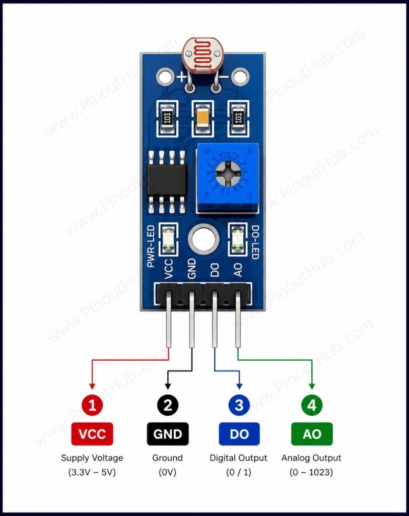
The LDR sensor module is available in two variants: a 3-pin version and a 4-pin version. The additional pin on the 4-pin module provides an analog output (AO), while both variants support digital output (DO).
4-pin header pinout
| Pin | Name | Type | Description |
|---|---|---|---|
| 1 | VCC | Power | Supply input — 3.3V to 5V |
| 2 | GND | Power | Ground |
| 3 | D0 | Output | Digital output — LOW in bright light; HIGH in darkness; threshold set by onboard potentiometer |
| 4 | A0 | Output | Analog output — voltage inversely proportional to light intensity; connect to a microcontroller ADC input |
Module construction
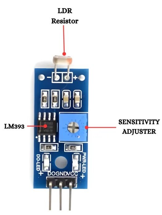
5mm CdS Photoresistor (LDR) A cadmium sulfide light-dependent resistor mounted on the top surface of the PCB. Resistance ranges from approximately 1MΩ in complete darkness to a few hundred ohms in bright light. The serpentine CdS track on its face maximises the active sensing area within the 5mm package.
Fixed Voltage Divider Resistor A fixed resistor in series with the LDR between VCC and GND. Together they form a voltage divider whose output voltage varies with LDR resistance and therefore with ambient light level.
LM393 Dual Comparator IC The signal processing IC. One comparator channel is used — its non-inverting input receives the analog voltage from the LDR divider, and its inverting input is connected to the potentiometer wiper. The open-collector output drives D0 LOW when the divider voltage drops below the reference.
Sensitivity Potentiometer An onboard trimmer potentiometer that sets the reference voltage on the inverting input of the LM393, defining the light intensity threshold at which D0 switches state.
Power Indicator LED Illuminates whenever VCC is applied to the module. Serves only as a power-on indicator.
Digital Output Indicator LED Connected to the D0 output line. Illuminates when D0 goes LOW, providing a visible confirmation that the brightness threshold has been crossed.
Specifications
| Parameter | Value |
|---|---|
| Supply Voltage | 3.3V – 5V DC |
| Output Drive Current | 15mA |
| Analog Output (A0) | 0V – VCC, inversely proportional to light |
| Digital Output (D0) | Active LOW (LOW = bright above threshold) |
| Comparator IC | LM393 |
| Sensing Element | 5mm CdS photoresistor |
| LDR Dark Resistance | ~1MΩ |
| LDR Bright Resistance | ~1kΩ – few hundred Ω |
| Sensitivity Adjustment | Onboard potentiometer |
| Power Indicator LED | Yes |
| Digital Output LED | Yes |
| Compatible Boards | Arduino, ESP32, Raspberry Pi |
Helpful resources
- Download the datasheet: here
- LDR Sensor Module with Arduino
- LDR Sensor Module with ESP32
- LDR Sensor Module with Raspberry Pi