The ZMPT101B is a single-phase AC voltage sensor module built around a high-precision current-type voltage transformer of the same name. By stepping down the AC mains voltage through galvanic isolation and conditioning the output through an onboard op-amp circuit, it produces a scaled analog voltage centered on a DC offset that can be read directly by any microcontroller ADC — allowing safe measurement of mains AC voltage without exposing the microcontroller to high-voltage circuits.
Pinout
Note: The ZMPT101B module has two separate sides — a high-voltage AC input side and a low-voltage DC signal side — which must never be mixed up during wiring. The AC input side carries mains voltage; the signal side connects to the microcontroller.
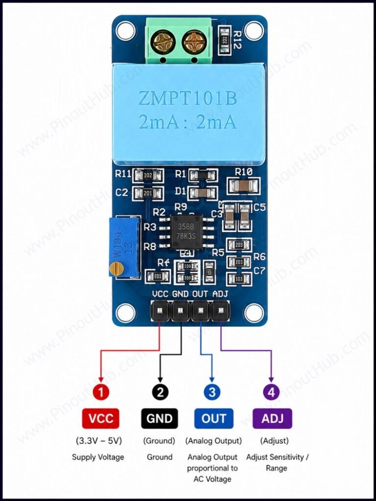
Signal side pinout (4-pin header)
| Pin | Name | Type | Description |
|---|---|---|---|
| 1 | VCC | Power | DC supply input — 5V recommended. |
| 2 | GND | Power | Ground for the signal circuit. |
| 3 | OUT | Output | Analog voltage output. |
| 4 | ADJ | Input | Adjustment pin — connects to the wiper of the multiturn potentiometer; used to fine-tune the output amplitude to match the ADC input range |
AC input side (2 screw terminals)
| Terminal | Name | Description |
|---|---|---|
| L | Line | AC mains live / hot wire input — carries lethal voltage |
| N | Neutral | AC mains neutral wire input — carries lethal voltage |
Output signal: With 5V supply and AC mains connected, the OUT pin produces a sine wave centered on 2.5V, swinging above and below this midpoint in proportion to the AC input voltage. With no AC input, the output sits at a flat 2.5V DC. The amplitude of the sine wave at the output depends on the potentiometer setting and must be calibrated against a known voltage reference before use.
Potentiometer adjustment: The multiturn trim potentiometer on the board adjusts the gain of the LM358 amplifier stage, controlling the peak-to-peak amplitude of the output waveform. Rotating it changes the output swing around the 2.5V midpoint — increasing it toward the ADC full-scale range improves resolution; reducing it prevents ADC clipping.
Module construction
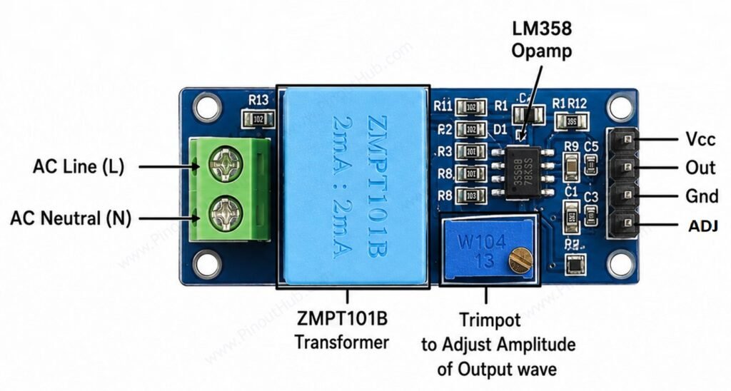
ZMPT101B Transformer A miniature epoxy-encapsulated current-type voltage transformer with a 1:1 turns ratio, 4kVRMS isolation voltage, ≤0.2% linearity, and a rated operating current of 1–2mA. Provides complete galvanic isolation between the AC mains input and the signal output circuit. Primary and secondary winding DC resistance is approximately 110Ω at 20°C.
Current-Limiting Resistor R1 A high-value resistor (820kΩ typical) in series with the AC input on the primary side. Converts the AC input voltage into a proportional primary current for the current-type transformer. Sets the operating current to approximately 1–2mA at full-scale input voltage.
Sampling Resistor R2 A low-value resistor (100Ω typical) across the secondary winding output. Converts the secondary current from the transformer back into a small AC voltage for the op-amp input stage.
LM358 Dual Op-Amp IC A two-stage band-pass amplifier built around the LM358. The first stage amplifies the small transformer secondary voltage; the second stage adds a DC offset of VCC÷2 to center the output waveform at the ADC midpoint. The LM358 operates from a single 5V–30V supply and draws very low quiescent current.
Multiturn Trim Potentiometer Adjusts the gain of the LM358 amplifier, controlling the peak-to-peak amplitude of the analog output waveform. Must be set during calibration so the output swing fits within the ADC input range without clipping.
Power Indicator LED Illuminates when VCC is applied to the signal side of the module. Serves only as a power-on indicator.
Screw Terminals (AC input side) Two screw terminals for connecting the AC mains L (live) and N (neutral) wires to the primary side of the transformer. These terminals carry lethal mains voltage and must be handled with appropriate safety precautions.
Specifications
| Parameter | Value |
|---|---|
| Supply | |
| Module Supply Voltage | 5V DC recommended / up to 30V DC |
| Transformer (ZMPT101B IC) | |
| Turns Ratio | 1000:1000 (1:1) |
| Rated Operating Current | 1 – 2mA |
| Isolation Voltage | 4000VRMS |
| Linearity | ≤0.2% |
| Phase Angle Error | ≤20′ at 2mA, 100Ω |
| Winding DC Resistance | ~110Ω at 20°C |
| Module | |
| AC Input Range | 0 – 250V AC |
| AC Frequency | 50Hz / 60Hz |
| Op-Amp IC | LM358 |
| Output Type | Analog voltage |
| Output DC Offset | VCC ÷ 2 (2.5V at 5V supply) |
| Output Amplitude | Adjustable via multiturn potentiometer |
| General | |
| Operating Temperature | −40°C to +70°C |
| Power Indicator | Yes (LED) |
| RoHS | Compliant |
Helpful resources
- Download the datasheet: here
- ZMPT101B with Arduino
- ZMPT101B with ESP32