The L3G4200D is an ultra-stable three-axis digital output gyroscope manufactured by STMicroelectronics that measures angular rate — how fast a device is rotating — around the pitch (X), roll (Y), and yaw (Z) axes simultaneously. By combining a MEMS sensing element with a CMOS IC interface on a single chip, it delivers 16-bit digital angular rate data over either I²C or SPI.
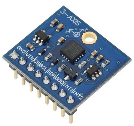
The sensor offers three user-selectable full-scale ranges — ±250, ±500, or ±2000 degrees per second — and supports both I²C and SPI serial interfaces. An embedded 32-level FIFO buffer allows the host microcontroller to batch-read angular rate data in bursts rather than polling continuously, significantly reducing MCU load. Two independently configurable interrupt pins allow the sensor to alert the host when data is ready or when angular rate exceeds a programmable threshold.
Pinout
Breakout module pinout (8-pin)
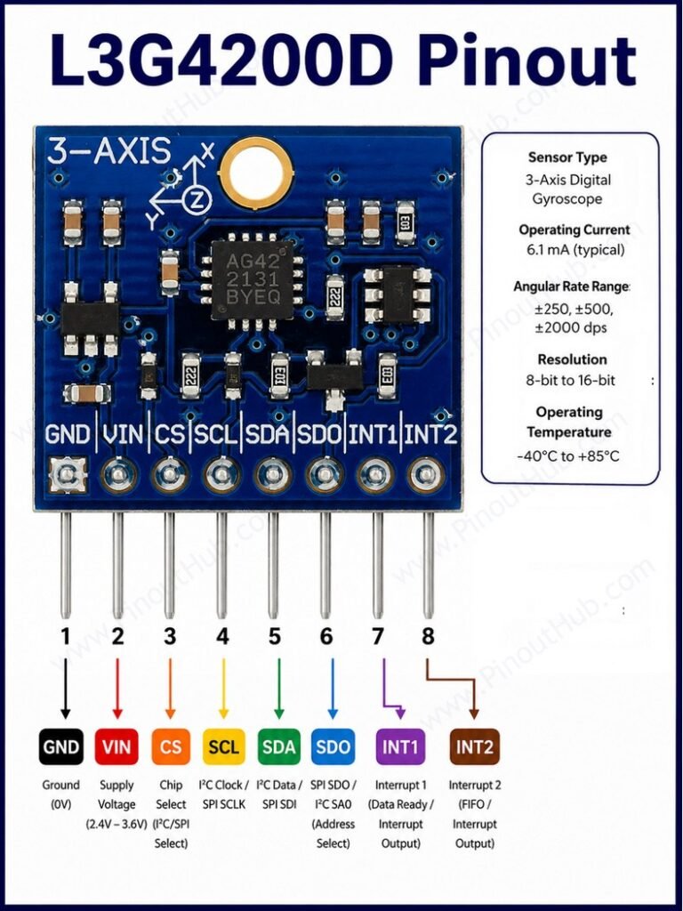
| Pin | Name | Type | Description |
|---|---|---|---|
| 1 | VIN | Power | Power supply input — accepts 2.5V to 5.5V via onboard regulator |
| 2 | VDD | Output | Regulated 3.3V output from the onboard regulator |
| 3 | GND | Power | Ground |
| 4 | SCL / SPC | Input | I²C clock / SPI clock — level-shifted to VIN |
| 5 | SDA / SDI | I/O | I²C data / SPI data in — level-shifted to VIN; doubles as SDO in 3-wire SPI mode |
| 6 | SDO | I/O | SPI data out (4-wire mode) / I²C address select — HIGH sets address to 0x69, LOW sets 0x68 |
| 7 | INT1 | Output | Programmable interrupt — fires when angular rate crosses a user-defined threshold |
| 8 | DRDY / INT2 | Output | Data ready signal — goes HIGH when new angular rate data is available; can also be configured as a FIFO watermark, overrun, or empty interrupt |
I²C address: The SDO pin doubles as the I²C address selector. Pulling SDO LOW sets the 7-bit address to 0x68; pulling it HIGH sets it to 0x69. This allows two L3G4200D sensors to coexist on the same I²C bus. Most breakout boards pull SDO HIGH through a 10kΩ resistor, making 0x69 the default address.
SPI mode: To use SPI, the CS pin (pulled HIGH by default on most boards) must be driven LOW to begin each transaction. The SPI interface operates in 4-wire mode by default, with separate SDI and SDO lines. 3-wire mode can be enabled via a register bit, after which SDI and SDO share a single pin.
L3G4200D Module Parts
L3G4200D Sensor IC A 16-pin 4 × 4 × 1.1mm LGA package combining the MEMS sensing element and CMOS IC interface on a single chip. Contains the three-axis vibrating gyroscope structure, three 16-bit ADCs, the FIFO buffer, low- and high-pass filters, the interrupt engine, and both I²C and SPI interface logic.
3.3V Voltage Regulator Most breakout boards include an onboard LDO that accepts up to 5.5V at the VIN pin and regulates it to the 3.3V the L3G4200D IC requires. The regulated output is also available on the VDD pin for powering other 3.3V peripherals.
Level Shifters Bidirectional logic level translators on the SCL/SPC and SDA/SDI lines allow the sensor to communicate with microcontrollers operating at any voltage from 2.5V to 5.5V, making it directly compatible with both 3.3V and 5V systems without external logic conversion.
Pull-up Resistors Onboard 10kΩ pull-up resistors on the SDA, SCL, and CS lines hold them at a high logic level when idle, as required by the I²C and SPI protocols. The SDO line is also pulled high through a 10kΩ resistor, setting the default I²C address to 0x69.
Decoupling Capacitors Placed close to the VDD and VDD_IO pins of the IC to suppress high-frequency supply noise. The L3G4200D datasheet also calls for an external low-pass filter on the PLLFILT pin for correct operation of the internal phase-locked loop, which most breakout boards implement with a small RC network.
Specifications
| Parameter | Value |
|---|---|
| Supply | |
| Supply Voltage (VDD) | 2.4V – 3.6V |
| Logic Voltage (VDD_IO) | 1.8V – VDD |
| Power Down Current | 5µA typical |
| Sleep Mode Current | 2.9mA typical |
| Normal Mode Current | 6.1mA typical |
| Gyroscope | |
| Full-Scale Range | ±250 / ±500 / ±2000 °/s |
| Sensitivity (±250 °/s) | 8.75 m°/s/digit |
| Sensitivity (±500 °/s) | 17.5 m°/s/digit |
| Sensitivity (±2000 °/s) | 70 m°/s/digit |
| ADC Resolution | 16-bit |
| Output Data Rate | 100 / 200 / 400 / 800 Hz |
| Zero-Rate Level (typical) | ±10 °/s |
| Interface | |
| Communication | I²C (up to 400kHz) / SPI (up to 10MHz) |
| I²C Address | 0x68 (SDO = 0) / 0x69 (SDO = 1) |
| General | |
| FIFO Buffer | 32 levels per axis |
| Interrupt Pins | INT1 (threshold) / DRDY-INT2 (data ready / FIFO) |
| Operating Temperature | −40°C to +85°C |
| Package | 16-pin LGA, 4 × 4 × 1.1mm |
| Status | End of Life — successor: L3GD20H |
| RoHS | Compliant |
Helpful resources
- Download the datasheet: here
- L3G4200D with Arduino
- L3G4200D with Raspberry Pi