The soil moisture sensor is a two-part resistive module that detects the water content of soil by measuring the electrical conductivity between two exposed electrode probes. As soil moisture increases, conductivity rises and resistance between the probes drops, causing the analog output voltage to change proportionally. A separate comparator board converts this continuous analog signal into a threshold-triggered digital output.
Pinout
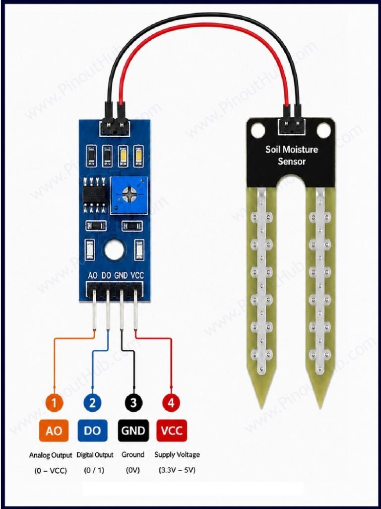
The soil moisture sensor system has two connectors — a 4-pin header on the comparator board for connection to the microcontroller, and a 2-pin screw terminal or connector where the probe cable attaches.
Comparator board pinout (4-pin)
| Pin | Name | Type | Description |
|---|---|---|---|
| 1 | A0 | Output | Supply input |
| 2 | D0 | Output | Ground |
| 3 | GND | Power | Digital output — LOW when soil moisture exceeds the set threshold; HIGH when dry |
| 4 | VCC | Power | Analog output — voltage proportional to soil moisture; connect to a microcontroller ADC input |
Probe connector (2-pin)
| Pin | Name | Description |
|---|---|---|
| 1 | + | VCC from comparator board |
| 2 | − | Signal / GND return to comparator board |
Digital output logic: The D0 pin is active LOW — it goes LOW when soil is wet and returns HIGH when soil dries below the threshold. This is the inverse of what some users expect. The onboard potentiometer sets the switching threshold; rotating it clockwise raises the reference voltage and requires higher moisture to trigger, while rotating it counter-clockwise lowers the threshold and makes the sensor trigger on lighter moisture levels.
Module construction
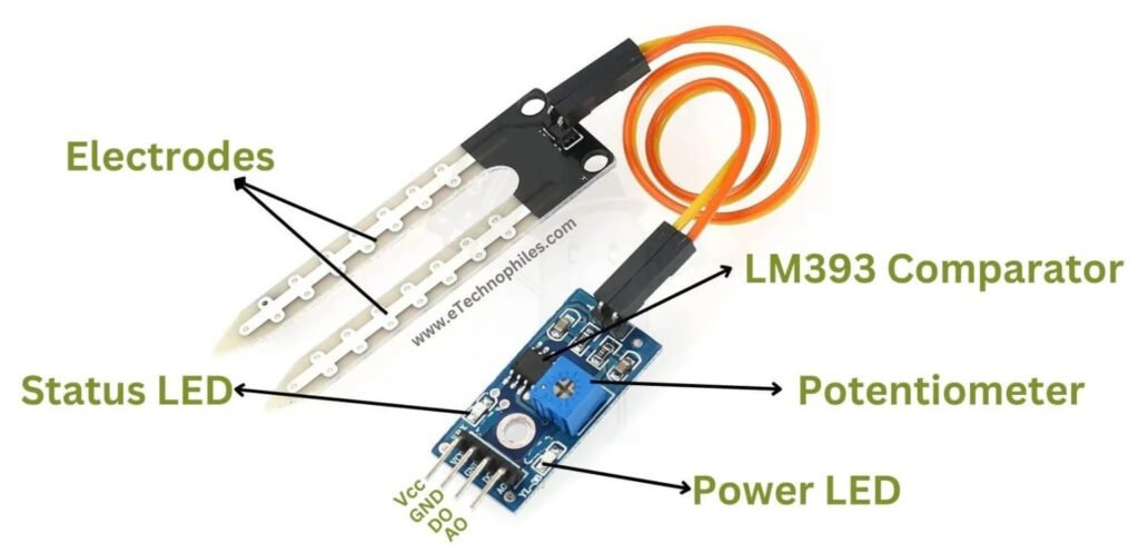
Soil Moisture Probe A fork-shaped PCB with two parallel conducting electrode tines. Quality probes use immersion gold plating over nickel to slow oxidation and extend service life; cheaper variants use bare nickel only. The tines act as a variable resistor when inserted into soil. Only the tines should be inserted into soil — the upper portion with the cable connection should remain above ground to minimise moisture exposure to the solder joints.
LM393 Dual Comparator IC The signal processing IC on the comparator board. One comparator channel is used — its non-inverting input receives the analog signal from the probe, and its inverting input is connected to the wiper of the 10kΩ potentiometer. The open-collector output drives D0 LOW when the probe voltage drops below the reference.
10kΩ Sensitivity Potentiometer A blue trimmer potentiometer on the comparator board that sets the reference voltage on the inverting input of the LM393. Rotating it clockwise raises the threshold, requiring wetter soil to trigger the digital output; counter-clockwise lowers it, making the sensor more sensitive to light moisture.
Power Indicator LED Illuminates whenever VCC is applied to the comparator board. Serves only as a power-on indicator.
Digital Output Indicator LED Connected to the D0 output line. Illuminates when D0 goes LOW, providing a visible confirmation that the moisture threshold has been crossed.
Decoupling Capacitor A small ceramic capacitor on the VCC line filters supply noise and prevents false triggers on the LM393 output.
Specifications
| Parameter | Value |
|---|---|
| Supply Voltage | 3.3V – 5V DC |
| Operating Current | 15mA |
| Analog Output (A0) | 0V – VCC, inversely proportional to moisture |
| Digital Output (D0) | Active LOW (LOW = soil wet above threshold) |
| ADC Range (10-bit) | ~200 (wet) to ~1023 (dry) |
| Comparator IC | LM393 |
| Sensitivity Potentiometer | 10kΩ trimmer |
| Power Indicator LED | Yes |
| Digital Output LED | Yes |
| PCB Size (comparator board) | 32 × 14mm (typical) |
| Compatible Boards | Arduino, ESP32, Raspberry Pi |
Helpful resources
- Download the datasheet: here
- Soil Moisture Sensor with Arduino
- Soil Moisture Sensor with ESP32
- Soil Moisture Sensor with Raspberry Pi