The TCS3200 is a programmable color light-to-frequency converter that detects the color of an object by measuring the intensity of red, green, and blue light reflected from its surface. By selecting different onboard photodiode filters and reading the resulting output frequency, it can identify a nearly limitless range of visible colors and deliver the result as a digital square wave — no analog-to-digital conversion required on the host side.
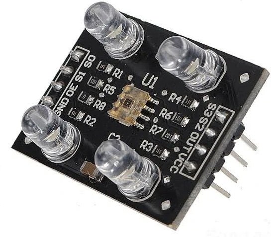
This makes the TCS3200 ideal for applications such as color sorting systems, test strip reading, ambient light sensing, color matching, and automated quality control in industrial environments. Its digital output interface, wide supply voltage range, and direct compatibility with microcontrollers have made it a popular choice for makers, engineers, and students alike.
Watch out for counterfeits: The TCS3200 is widely cloned. Genuine units are manufactured by ams (formerly TAOS — Texas Advanced Optoelectronic Solutions). Counterfeit parts may produce incorrect frequency outputs or fail to respond correctly to filter selection. Always source from reputable suppliers and verify behavior against the expected frequency ranges in the datasheet.
Pinout
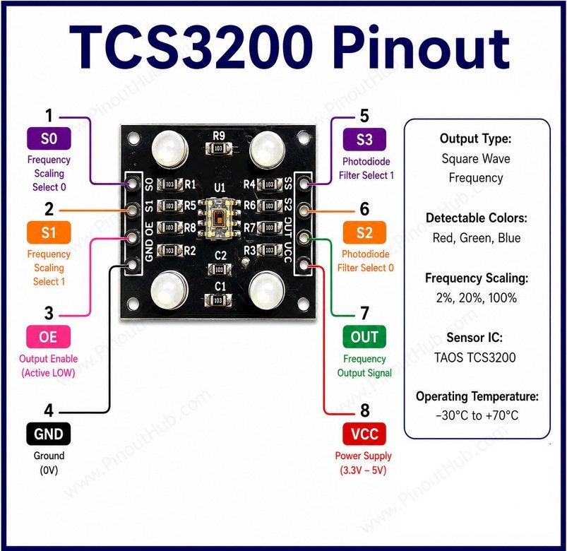
The bare TCS3200 IC is an 8-pin SOIC package. In maker applications it is almost always used on a breakout module that adds four white LEDs, a lens, and an 8-pin header for easy connection.
Breakout module pinout (8-pin)
| Pin | Name | Type | Description |
|---|---|---|---|
| 1 | S0 | Input | Output frequency scale select bit 0 — combined with S1 to set frequency scaling. |
| 2 | S1 | Input | Output frequency scale select bit 1 — combined with S0 to set frequency scaling. |
| 3 | OE | Input | Output enable — active LOW; pull HIGH to disable the output (high-impedance state). |
| 4 | GND | Power | Ground (0V). |
| 5 | S3 | Input | Photodiode filter select bit 1 — combined with S2 to choose red, green, blue, or clear filters. |
| 6 | S2 | Input | Photodiode filter select bit 0 — combined with S3 to choose red, green, blue, or clear filters. |
| 7 | OUT | Output | Square-wave output whose frequency is proportional to the intensity of the selected color. |
| 8 | VCC | Power | Supply voltage (typically 2.7V to 5.5V). |
Filter selection (S2/S3):
| S2 | S3 | Active Filter |
|---|---|---|
| LOW | LOW | Red |
| LOW | HIGH | Blue |
| HIGH | LOW | Clear (no filter) |
| HIGH | HIGH | Green |
Frequency scaling (S0/S1):
| S0 | S1 | Output Scaling |
|---|---|---|
| LOW | LOW | Power down (output Hi-Z) |
| LOW | HIGH | 2% |
| HIGH | LOW | 20% |
| HIGH | HIGH | 100% |
For most Arduino applications, 20% scaling (S0 HIGH, S1 LOW) is recommended, as 100% scaling can produce frequencies too high for accurate pulse measurement on slower microcontrollers.
Working principle
The TCS3200 detects color using optical filtering and frequency conversion rather than analog voltage levels, which makes it inherently more noise-resistant than analog color sensors.
Photodiode array and filtering: Light reflected from the target object strikes the 8×8 photodiode array on the sensor surface. When a filter type is selected via S2 and S3, only the 16 photodiodes with that filter become active. Each filter allows only its corresponding color wavelength to pass — red blocks blue and green, green blocks red and blue, and so on. This isolates the intensity of each color channel independently.
Current-to-frequency conversion: The combined photocurrent from the 16 active photodiodes flows into the internal current-to-frequency converter. A stronger light intensity produces a higher current, which in turn produces a higher output frequency on the OUT pin. The relationship is linear — doubling the light intensity roughly doubles the output frequency.
RGB measurement sequence: To determine the full color of an object, the host microcontroller activates each filter in sequence — red, green, then blue — and measures the output frequency for each. Comparing the three frequency values gives the relative intensity of each color channel, from which the object’s color can be calculated or matched against a reference.
White balance calibration: Before taking color readings, the sensor should be calibrated by placing a white reference surface at the working distance and recording the frequency outputs for each channel. These values set the 100% reference point for each color, correcting for variations in LED brightness and sensor sensitivity across channels.
Frequency scaling: The S0/S1 scaling pins allow the output frequency range to be reduced to 20% or 2% of full scale, which slows the output down enough to be measured accurately by standard microcontroller timers at a lower clock speed.
TCS3200 module construction
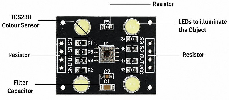
TCS3200 Sensor IC A single monolithic CMOS IC in an 8-pin SOIC package. Contains the entire 8×8 filtered photodiode array, the current-to-frequency converter, the output frequency scaling dividers, and the digital control logic — all in one chip. The photoactive area is 1mm × 1mm, and each photodiode measures 110µm × 110µm on 134µm centers.
Four White LEDs Mounted at the corners of the breakout module PCB surrounding the sensor IC. They illuminate the target object from close range to ensure sufficient and consistent reflected light reaches the sensor. Many modules include a control pin or solder jumper to gate the LEDs on and off, which allows ambient light subtraction by taking a reading with LEDs off and subtracting it from the reading with LEDs on.
Lens A 5.6mm lens on some module variants focuses the field of view and defines a consistent working distance — typically around 1cm from the sensor surface to the target object. Operating too far from the target reduces reflected light intensity and degrades accuracy.
Decoupling Capacitors Onboard bypass capacitors on the VCC supply rail filter high-frequency noise generated by the LED switching and the internal oscillator, keeping the supply clean for accurate frequency output.
Specifications
The key specifications of the sensor are listed below.
| Parameter | Value |
|---|---|
| Supply Voltage | 2.7V – 5.5V |
| Supply Current (active) | ~2mA (sensor only) |
| Output Type | Digital square wave, 50% duty cycle |
| Output Frequency (full scale) | 2Hz – 500kHz |
| Frequency Scaling Options | 2%, 20%, 100% |
| Photodiode Array | 8×8, 64 photodiodes (16 per color + 16 clear) |
| Photodiode Size | 110µm × 110µm |
| Photoactive Area | 1mm × 1mm |
| Red wavelength peak | ~580nm |
| Green wavelength peak | ~540nm |
| Blue wavelength peak | ~450nm |
| Operating Temperature | −40°C to +70°C |
| Package (bare IC) | 8-pin SOIC |
| RoHS | Compliant |
Helpful resources
- Download the datasheet: here
- TCS3200 with Arduino
- TCS3200 with ESP32
- TCS3200 with Raspberry Pi