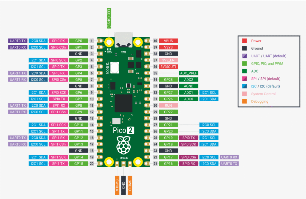
The Raspberry Pi Pico 2 is a powerful microcontroller board based on the RP2350 chip. It brings improved performance, more memory, and enhanced peripherals while keeping the same familiar pin layout as the original Pico.
It features 26 multifunction GPIO pins, supporting digital I/O, ADC, PWM, UART, SPI, and I2C interfaces.
Note: This pinout guide holds true for both variants of Pico 2(with and without wireless capabilities).
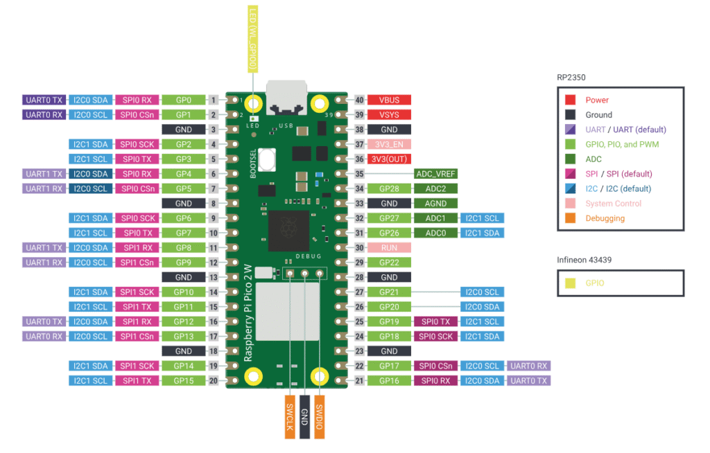
Pico 2W Pinout Overview
Note: The only difference in the pin diagram of Pico 2 and 2W is the position of the debug pins: The debug pins on Pico 2 are at the bottom of the board, whereas on 2W, they are at the center.
- Total 40 physical pins (DIP layout)
- 26 GPIO pins available for general use
- Remaining pins include:
- Power (VBUS, VSYS, 3.3V)
- Ground (GND)
- ADC reference & control pins
- Debug (SWD) pins
Each GPIO pin is multi-functional, meaning it can be configured for different interfaces like SPI, I2C, UART, or PWM depending on your code
Power Pins
The Raspberry Pi Pico 2 provides multiple power input and output options, making it flexible for different project setups—from USB-powered to battery-operated systems.
VBUS
- Connected directly to the USB power (5V)
- Active only when the board is powered via USB
- Can be used to power external components (limited current)
VSYS
- Main input voltage pin
- Accepts a voltage range of ~1.8V to 5.5V
- Used when powering the board from:
- Batteries
- External power supplies
This is the most commonly used pin for external power input.
3V3 (OUT)
- Regulated 3.3V output from the onboard regulator
- Used to power:
- Sensors
- Modules
- External circuits
Keep current draw within safe limits (typically ~300mA total depending on usage)
3V3_EN
- Used to enable or disable the 3.3V regulator
- Pulling this pin LOW will turn off the board
- Useful for low-power applications
GND (ground)
- Multiple ground pins available across the board
- All GND pins are internally connected
- Essential for completing circuits
ADC (Analog Input) Pins
The Raspberry Pi Pico 2 includes 3 ADC (Analog-to-Digital Converter) pins, allowing it to read analog signals such as voltage from sensors, potentiometers, or other analog devices.
ADC Pin List
- GP26 → ADC0
- GP27 → ADC1
- GP28 → ADC2
Resolution & range
- 12-bit ADC resolution
- Values range from 0 to 4095
- Input voltage range:
- 0V to 3.3V
PWM Pins
The Raspberry Pi Pico 2 supports PWM (Pulse Width Modulation) on almost all GPIO pins, making it ideal for controlling brightness, motor speed, and other analog-like outputs.
PWM architecture (Important)
The RP2350 uses PWM slices. Each slice has: 2 channels (A & B)
Total: Multiple PWM slices shared across GPIOs. Total 16 PWM channels.
This means:
- Some pins share the same PWM slice
- You may not get independent control of all pins simultaneously
SPI pins(Flash and general SPI)
Default SPI Pins (SPI0)
- MISO → GP16
- CS (Chip Select) → GP17
- SCK (Clock) → GP18
- MOSI → GP19
Secondary SPI (SPI1)
- MISO → GP12
- CS → GP13
- SCK → GP10
- MOSI → GP11
Internal SPI
- The Pico 2 uses SPI internally to communicate with the onboard flash memory
- These pins are:
- Not exposed for general use
- Should not be interfered with
I2C pins
Default I2C Pins (I2C0)
- SDA (Data) → GP4
- SCL (Clock) → GP5
Secondary I2C (I2C1)
- SDA → GP2
- SCL → GP3
UART pins
Default UART Pins (UART0)
- TX (Transmit) → GP0
- RX (Receive) → GP1
Secondary UART (UART1)
- TX → GP4
- RX → GP5
Pins with special functions
GP25 – Onboard LED
- Connected to the built-in LED
- Useful for:
- Testing code
- Debugging
You can still use it as a normal GPIO, but it will also control the onboard LED.
RUN Pin
- Used to reset or restart the microcontroller
- Pulling it LOW will reboot the board
BOOTSEL button
- Not a GPIO pin, but important
- Used to:
- Enter bootloader mode
- Upload code via USB
SWD Pins (debugging)
- Used for low-level debugging/programming
- Includes:
- SWDIO
- SWCLK
Avoid using these unless you specifically need debugging features.
Specifications
Core Specifications
| Parameter | Details |
|---|---|
| Microcontroller | RP2350 |
| CPU | Dual-core Arm Cortex-M33 / RISC-V Hazard3 |
| Clock Speed | Up to 150 MHz |
| SRAM | 520 KB |
| Flash Memory | 4 MB (onboard) |
Connectivity
| Parameter | Details |
|---|---|
| USB | USB 1.1 (Device & Host) |
| SPI | 2 × SPI controllers |
| I2C | 2 × I2C controllers |
| UART | 2 × UART controllers |
| PIO | Programmable I/O supported |
GPIO & Analog
| Parameter | Details |
|---|---|
| GPIO Pins | 26 multi-function GPIOs |
| ADC Channels | 3 (12-bit) |
| PWM | Available on most GPIO pins |
| Logic Level | 3.3V (Not 5V tolerant) |
Power
| Parameter | Details |
|---|---|
| Input Voltage (VSYS) | ~1.8V to 5.5V |
| Operating Voltage | 3.3V |
| Power Sources | USB (VBUS) / External (VSYS) |
Other features
| Parameter | Details |
|---|---|
| Temperature Sensor | Internal |
| Onboard LED | GP25 |
| Debug Interface | SWD |
| Programming | USB drag-and-drop |
| Low Power Modes | Supported |
*Pico 2W features(not in Pico 2)
- Wi-Fi (802.11n): Single-band (2.4 GHz).
- Bluetooth 5.2: Support for Bluetooth Low Energy (BLE) Central and Peripheral roles.
Note: PICO 2W is identical to PICO 2 in all aspects except having wireless features.
Important usage notes
- GPIO works on 3.3V (not 5V tolerant)
- Don’t power VBUS and VSYS together
- GPIO current is limited → avoid driving heavy loads directly
- Always use a common ground with external devices
- Check pin multiplexing before assigning functions
- Use voltage dividers / level shifters when needed
- Avoid using flash & SWD pins
- Ensure stable power supply for reliable operation
- Use VSYS for batteries, USB for development
- Start testing with simple components (like GP25 LED)
Helpful resources
- Watch this introductory video
2. Important information about Pico 2 variants
3. Download the Pico 2 datasheet from here