NodeMCU ESP8266 features a 32-bit Tensilica L106 processor and onboard Wi-Fi based on ESP-12E/F, exposing multiple GPIO pins for interfacing. The board operates at 3.3V logic levels and supports interfaces such as GPIO, ADC, SPI, I2C (software), UART, and PWM.
Pinout
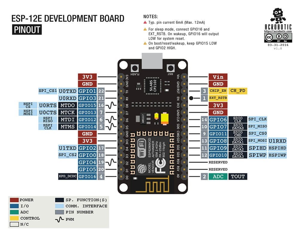
| NodeMCU Label | GPIO | Common Function |
|---|---|---|
| D0 | GPIO16 | Deep sleep wake (no PWM/interrupt) |
| D1 | GPIO5 | I²C SCL |
| D2 | GPIO4 | I²C SDA |
| D3 | GPIO0 | Boot config pin |
| D4 | GPIO2 | Built-in LED (often) |
| D5 | GPIO14 | SPI SCLK |
| D6 | GPIO12 | SPI MISO |
| D7 | GPIO13 | SPI MOSI |
| D8 | GPIO15 | SPI CS / boot config |
| RX | GPIO3 | UART RX |
| TX | GPIO1 | UART TX |
| A0 | ADC0 | Analog input |
Specifications
| Feature | Details |
|---|---|
| SoC | Espressif ESP8266EX |
| CPU | Tensilica L106 @ 80–160 MHz |
| Wi-Fi | 2.4 GHz 802.11 b/g/n |
| Flash | Typically 4MB |
| GPIO pins | ~11 usable (Total: 17) |
| ADC | 1 channel (10-bit) |
| UART | 2 (1 full + 1 TX-only) |
| SPI | Supported |
| Logic level | 3.3V |
| Power input | 5V via Micro-USB or VIN |
Compatibility
- 3.3V logic level
- Built-in Wi-Fi
- Breadboard friendly
- Micro-USB powered
- Limited ADC (1 channel)
- Boot-sensitive pins
Usage notes
- GPIO operate at 3.3V only and are not 5V tolerant
- Some pins affect boot mode:
- GPIO0, GPIO2, GPIO15 must be in correct states during boot
- GPIO16 does not support interrupts or PWM
- ADC input range is 0–1V on the chip (NodeMCU boards often include divider to allow 3.3V)
- Limited number of GPIO compared to ESP32
- Wi-Fi activity can affect timing-sensitive tasks
Helpful resources
- Tutorial videos: Mini course
2. Datasheet(ESP-12E)
3. Projects based on ESP8266(video)