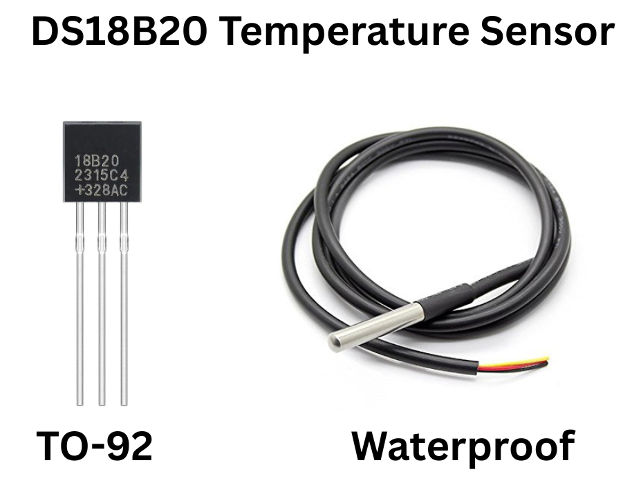
If you need to measure temperature across a long cable, in wet environments, or from a dozen different points using a single wire, the DS18B20 is the sensor built for that job. It is a digital temperature sensor that communicates over the 1-Wire protocol, and shows up everywhere from aquarium controllers and soil monitoring systems to industrial pipeline sensing and home heating setups. It’s available in a TO-92 package as well.
What is DS18B20?
The DS18B20 is a precision digital temperature sensor that communicates over Maxim’s 1-Wire protocol. Unlike analog sensors, it outputs a fully digital temperature reading directly, eliminating the need for any ADC conversion on the microcontroller side.
One of the biggest advantages of the DS18B20 is its 1-Wire bus capability — multiple DS18B20 sensors can share a single data line simultaneously, each identified by a unique 64-bit serial address burned at the factory. This makes it ideal for multi-point temperature monitoring across large installations using minimal wiring.
DS18B20 overview
| Parameter | Value |
|---|---|
| Sensor Type | Digital Temperature Sensor |
| Operating Voltage | 3.0V – 5.5V |
| Current Consumption | 1.5mA (during conversion) |
| Temperature Range | -55°C to +125°C |
| Output Type | Digital (1-Wire) |
| Sensitivity | 0.0625°C (at 12-bit resolution) |
| Accuracy | ±0.5°C (from -10°C to +85°C) |
| Communication | 1-Wire Serial |
| Mounting Type | Through Hole |
| Compatible Boards | Arduino Uno, ESP32, Raspberry Pi |
Pinout
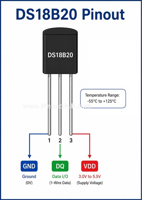
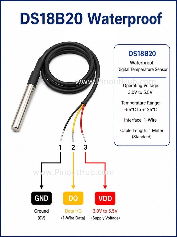
| Pin Name | Type | Description |
|---|---|---|
| GND | Power | Ground connection |
| DQ | Data | 1-Wire data input/output |
| VDD | Power | Supplies power to the sensor (3.0V – 5.5V) |
Note: A pull-up resistor of 4.7kΩ is required between the DQ pin and VDD for proper 1-Wire communication. The DS18B20 can also operate in parasite power mode, drawing power directly from the DQ line with VDD connected to GND.
Working Principle
The DS18B20 works by using a temperature-sensitive oscillator circuit whose frequency changes with temperature. An internal counter compares this against a reference clock and calculates the precise temperature digitally, outputting the result over the 1-Wire bus.
The sensor communicates using Maxim’s 1-Wire protocol. When the host microcontroller sends a conversion command, the DS18B20 begins measuring and stores the result in a 9-byte scratchpad memory. The host then issues a read command to retrieve the data:
- Bytes 0–1: Temperature register (16-bit signed integer)
- Bytes 2–3: Alarm high and low registers
- Byte 4: Configuration register (sets resolution)
- Bytes 5–7: Reserved
- Byte 8: CRC checksum
The resolution is user-configurable from 9-bit to 12-bit, directly trading off conversion speed for precision:
| Resolution | Precision | Conversion Time |
|---|---|---|
| 9-bit | 0.5°C | 93.75ms |
| 10-bit | 0.25°C | 187.5ms |
| 11-bit | 0.125°C | 375ms |
| 12-bit | 0.0625°C | 750ms |
Since the output is fully digital with built-in CRC error checking, readings are immune to noise and voltage drop across long cable runs — a significant advantage over analog sensors in real-world installations.
Internal circuitry of the DS18B20
Although the DS18B20 looks like a standard 3-pin transistor package, it contains several sophisticated components inside its IC.
1. Temperature-Sensitive Oscillator The primary sensing element — an oscillator whose frequency varies predictably with temperature, forming the basis for all measurements.
2. Reference Oscillator A stable reference clock that the internal counter compares against the temperature-sensitive oscillator to calculate the precise temperature value.
3. 64-bit ROM (Laser-Programmed) A factory-written unique address that allows multiple DS18B20 sensors to share a single 1-Wire bus and be addressed individually by the host.
4. Scratchpad Memory (SRAM) 9 bytes of working memory that hold the latest temperature reading, alarm thresholds, configuration register, and CRC byte for data integrity verification.
5. EEPROM Non-volatile memory that retains the alarm thresholds and resolution configuration even when power is removed.
6. Parasite Power Circuit An internal capacitor that can store enough charge from the DQ line to power the sensor during conversions, allowing operation with just two wires (DQ + GND) instead of three.
Specifications
| Parameter | Value |
|---|---|
| Supply Voltage | 3.0V – 5.5V |
| Supply Current | 1.5mA (during conversion), 1µA (standby) |
| Temperature Range | -55°C to +125°C |
| Accuracy | ±0.5°C (from -10°C to +85°C) |
| Resolution | 9-bit to 12-bit (user configurable) |
| Conversion Time | 93.75ms (9-bit) to 750ms (12-bit) |
| Communication | 1-Wire (single data line) |
| Pull-up Resistor | 4.7kΩ (required) |
| Parasite Power | Supported (2-wire operation) |
| Unique Address | 64-bit laser-programmed ROM |
| Multi-drop Support | Up to 100+ sensors on one bus |
| CRC | 8-bit CRC for data integrity |
| Operating Temperature | -55°C to +125°C |
| Storage Temperature | -55°C to +125°C |
| Package Types | TO-92, SO-8, µSOP |
| Cable Length | Up to 100m (with proper pull-up) |
Practical Projects
Download the datasheet: PDF here