The BNO055 is an intelligent 9-axis absolute orientation sensor that combines a triaxial accelerometer, gyroscope, and magnetometer with an onboard 32-bit microcontroller running dedicated sensor fusion firmware, all inside a single package. By processing all three sensor inputs internally, it outputs ready-to-use orientation data directly, with no fusion algorithm required on the host side.
This makes the BNO055 ideal for applications that require accurate, drift-corrected orientation tracking, such as robotics, drones, virtual and augmented reality, navigation systems, and motion-controlled wearables. Its onboard sensor fusion, simple digital interface, and low power consumption have made it a favorite for makers who want professional-grade orientation data without writing their own fusion algorithm.
What is BNO055?
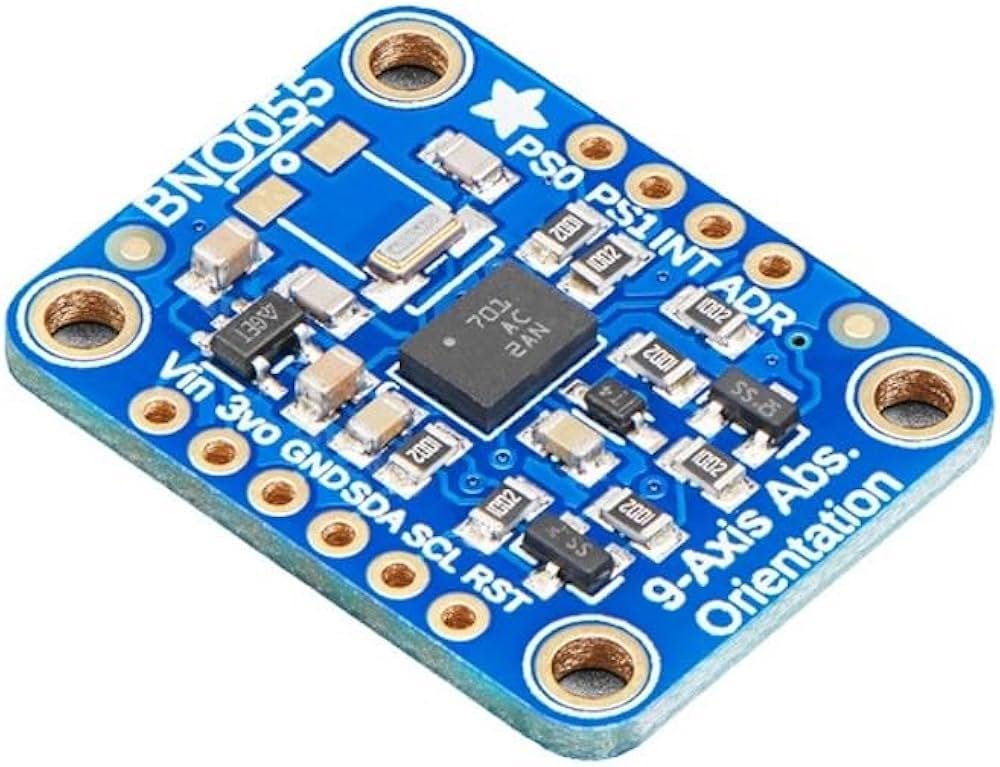
The BNO055 is a System in Package (SiP) device. It integrates a triaxial 14-bit accelerometer, a triaxial 16-bit gyroscope with a range of up to ±2000 degrees per second, a triaxial geomagnetic sensor, and a 32-bit Cortex M0+ microcontroller running dedicated sensor fusion software, all in a single package. These chip-sets are combined into one 28-pin LGA housing measuring 3.8 × 5.2 × 1.1mm. For optimum system integration, the BNO055 is equipped with digital bidirectional I²C and UART interfaces.
Unlike a standard 9-axis IMU that hands raw or lightly-processed data to the host, the embedded Cortex M0+ runs the entire sensor fusion algorithm onboard. It outputs fully fused sensor data including quaternions, Euler angles, rotation vectors, linear acceleration, gravity vectors, and heading — the host simply reads the finished result over I²C or UART.
Watch out for clones: The BNO055 is also sold pre-mounted on breakout boards by various third-party manufacturers. Pinout and pin count can vary slightly between these boards, so always check the silkscreen labeling on your specific module before wiring.
BNO055 overview
| Parameter | Value |
|---|---|
| Sensor Type | 9-Axis Absolute Orientation Sensor (SiP) |
| Accelerometer | Triaxial, 14-bit |
| Gyroscope | Triaxial, 16-bit, up to ±2000°/s |
| Magnetometer | Triaxial geomagnetic sensor |
| Onboard Processor | 32-bit ARM Cortex M0+ |
| Fusion Output | Quaternion, Euler angles, rotation vector, linear acceleration, gravity, heading |
| Supply Voltage (module) | 3.3V – 5V |
| Logic Level (chip) | 3.3V |
| Communication | I²C / UART |
| I²C Address | 0x28 (default) / 0x29 (ADR/ADD pin high) |
| Power Modes | Normal, Low Power, Suspend |
| Operating Temperature | −40°C to +85°C |
| Package | 28-pin LGA, 3.8 × 5.2 × 1.1mm |
| Compatible Boards | Arduino, ESP32 (with caveats), Raspberry Pi, BeagleBone Black |
Pinout
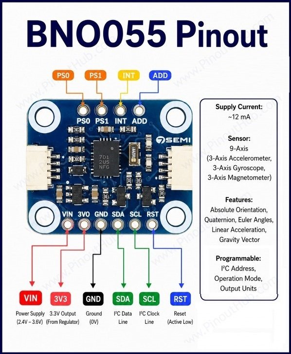
| Pin | Name | Type | Description |
|---|---|---|---|
| 1 | VIN | Power | Power input — accepts 3.3V to 5V |
| 2 | 3V3 | Output | Regulated 3.3V output from the onboard regulator |
| 3 | GND | Power | Ground |
| 4 | SDA | I/O | I²C data pin — usable with 3V or 5V logic; most boards include a pull-up resistor |
| 5 | SCL | Input | I²C clock pin — usable with 3V or 5V logic; most boards include a pull-up resistor |
| 6 | RST | Input | Hardware reset pin — pull low then high to reset the module; can normally be left unconnected |
| 7 | ADD / ADR | Input | I²C address selection — pulling high changes the address from 0x28 to 0x29 |
| 8 | INT | Output | Interrupt output — used for motion detection or data-ready signaling |
| 9 | PS0 | Input | Protocol select bit 0 — sets I²C or UART mode |
| 10 | PS1 | Input | Protocol select bit 1 — sets I²C or UART mode |
Protocol selection: Setting both PS0 and PS1 to LOW enables I²C mode. For UART mode, connect PS0 to VCC and PS1 to GND. On boards with two header rows, both rows — VIN/GND/SDA/SCL and PS0/PS1 — must be soldered to access the protocol pins.
Working principle
The BNO055 contains three independent MEMS sensing systems feeding directly into an onboard Cortex M0+ microcontroller, which performs all sensor fusion internally before data ever reaches the host.
Accelerometer A 14-bit triaxial accelerometer measures linear acceleration along each axis, including gravity. This data anchors the tilt reference used to correct gyroscope drift.
Gyroscope A 16-bit triaxial gyroscope with a range of up to ±2000 degrees per second measures angular rate around each axis. As with any gyroscope, integrating this data over time accumulates drift, which the fusion algorithm corrects using the accelerometer and magnetometer.
Magnetometer A triaxial geomagnetic sensor measures the Earth’s magnetic field to determine absolute heading, solving the yaw drift problem that gyroscope and accelerometer data alone cannot resolve.
Onboard sensor fusion: The BNO055 uses its three triple-axis sensors to simultaneously measure tangential acceleration via the accelerometer, rotational acceleration via the gyroscope, and the strength of the local magnetic field via the magnetometer. Rather than requiring weeks of algorithm development to combine these signals accurately, the BNO055 performs sensor fusion onboard and delivers meaningful orientation data within minutes of integration. Available power modes include normal, low power, and suspend, allowing the host to manage overall system power consumption.
Hardware Components of the BNO055
Sensor IC (SiP) The core of the module is a single 28-pin LGA package measuring 3.8 × 5.2 × 1.1mm. Inside this one package are the triaxial accelerometer, triaxial gyroscope, triaxial magnetometer, and the 32-bit Cortex M0+ fusion processor — all the sensing and computation needed for absolute orientation output lives on this single chip.
Onboard Voltage Regulator Breakout modules include a small LDO regulator that accepts a wider input range (typically 3.3V–5V at VIN) and steps it down to the 3.3V the BNO055 chip itself requires internally. The regulated 3.3V is also broken out separately (often labeled 3V3) so it can power other 3.3V peripherals in the same circuit.
Pull-up Resistors Most breakout boards include onboard pull-up resistors on the SDA and SCL lines (commonly around 10kΩ), holding the I²C bus lines high when idle, as required by the I²C protocol. No external pull-ups are typically needed for standard single-device I²C operation.
Protocol Select Header A separate header row exposes the PS0 and PS1 pins, which configure the chip’s communication mode. These are normally tied low (I²C mode) by onboard pull-downs but can be overridden to switch into UART mode for platforms where I²C is problematic.
Reset and Interrupt Pins The RST pin allows the host to force a hardware reset of the onboard fusion processor without cycling power to the whole board. The INT pin can be configured to flag specific events, such as a new orientation reading being ready — so the host doesn’t need to constantly poll the sensor over the bus.
Address Select Pin The ADD (or ADR) pin lets two BNO055 modules share the same I²C bus. Leaving it low keeps the default address of 0x28; pulling it high shifts the device to 0x29, avoiding an address collision with a second unit.
Specifications
| Parameter | Value |
|---|---|
| Supply Voltage (VIN, module) | 3.3V – 5V |
| Logic Voltage (chip) | 3.3V |
| Accelerometer Resolution | 14-bit |
| Gyroscope Resolution | 16-bit |
| Gyroscope Range | Up to ±2000°/s |
| Magnetometer Type | Triaxial geomagnetic sensor |
| Onboard Processor | 32-bit ARM Cortex M0+ |
| Fusion Outputs | Quaternion, Euler angles, rotation vector, linear acceleration, gravity, heading |
| Communication | I²C / UART |
| I²C Address | 0x28 default / 0x29 (ADD high) |
| Power Modes | Normal / Low Power / Suspend |
| Operating Temperature | −40°C to +85°C |
| Compliance | RoHS compliant, halogen-free |
| Package | 28-pin LGA, 3.8 × 5.2 × 1.1mm |
Helpful resources
- Download the datasheet: here
- BNO055 with Arduino: tutorial
- BNO055 with ESP32