Arduino Nano 33 BLE Rev 2 is based on the Nordic nRF52840 SoC, featuring a 32-bit ARM Cortex-M4F core running at 64 MHz. It integrates Bluetooth Low Energy (BLE) connectivity and exposes multiple GPIO pins through Nano-style headers.
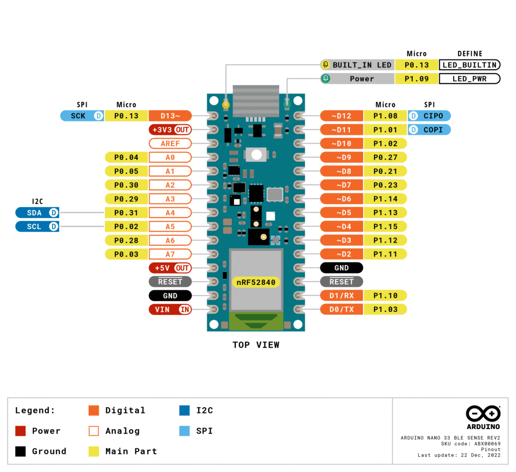
Official Pinout
Power management & low power modes
The board is designed for battery-operated efficiency, but it requires careful jumper management on the bottom of the PCB.
- VIN Pin: Accepts 5V to 18V. If used, it automatically disconnects the USB power source.
- 3.3V Pin: Output from the onboard regulator.
- Ultra-Low Power Hack: To bypass the regulator and save every micro-amp, you can cut the 3V3 jumper on the back and power the board directly with a 3.3V battery.
- 5V Pin: By default, this pin is inactive. To output 5V (from USB or VIN), you must short the VUSB jumper on the back.
- LED ON: A power indicator tied to the 5V rail (USB or VIN).
Digital & PWM pins
All 14 digital pins (D0–D13) can be used for general input and output.
- PWM: Unlike the standard Nano, all digital pins on the Nano 33 BLE can support PWM (Pulse Width Modulation).
- Logic Level: Strictly 3.3V. Connecting a 5V sensor signal directly to these pins will likely fry the microcontroller.
Analog pins
There are 8 analog input pins (A0–A7).
- Resolution: While the standard Arduino uses 10-bit resolution, this board supports up to 12-bit resolution, providing a range of 0 to 4095.
- A4 (SDA) and A5 (SCL): These are specifically assigned for I2C communication.
Communication interfaces
The Nano 33 BLE is one of the few boards that can act as both a Bluetooth® Client and Host.
| Interface | Pins | Specialized Notes |
| I2C | A4 (SDA), A5 (SCL) | Warning: These have internal pull-up resistors. Usage as analog inputs is NOT recommended. |
| NFC | D7 & D8 | You can attach an external NFC antenna here to emulate an NFC tag. |
| UART | D0 (RX), D1 (TX) | Dedicated hardware serial for high-speed communication. |
| SPI | D11 (COPI), D12 (CIPO), D13 (SCK) | Standard SPI for peripheral displays or SD cards. |
Onboard sensors & internal pins
The “Sense” version of this board includes a suite of sensors, but even the standard BLE version has internal connections you should know:
- Built-in LED: Connected to D13.
- RGB LED: This is a common-anode LED. To turn a color on, you must write the pin
LOW.- Red:
LEDR - Green:
LEDG - Blue:
LEDB
- Red:
- I2C Bus: The onboard IMU (Inertial Measurement Unit) is connected to the same I2C bus as A4/A5.
Specifications
| Feature | Specification |
| Microcontroller | nRF52840 (32-bit ARM® Cortex®-M4) |
| Operating Voltage | 3.3V (Not 5V tolerant) |
| Input Voltage (Limit) | 5V – 21V (Nominal: 5V – 18V) |
| Clock Speed | 64 MHz |
| Flash Memory | 1 MB |
| SRAM | 256 KB |
| Digital I/O Pins | 14 (All can be used for PWM & Interrupts) |
| Analog Input Pins | 8 (12-bit resolution ADC) |
| DC Current per I/O Pin | 10 mA – 15 mA (Conservative limit) |
| Bluetooth | Bluetooth® Low Energy 5.0 (NINA-B306 module) |
| IMU (9-axis) | BMI270 (6-axis) + BMM150 (3-axis Magnetometer) |
| USB Connector | Micro USB |
| Interfaces | UART, SPI, I2C |
| Board Dimensions | 45 mm x 18 mm |
Important usage notes
- 3.3V Limit: The pins are not 5V tolerant. 5V signals will damage the board.
- New IMU Library: Rev 2 uses the BMI270 (6-axis) and BMM150 (3-axis) sensors. You must use the
Arduino_BMI270_BMM150library instead of the oldLSM9DS1library. - VUSB Jumper: The solder bridge to enable 5V on the VUSB pin has moved to the top side of the board for easier access.
- Improved Power: It uses a new step-down converter (MP2322), which is more efficient but retains the same voltage limits.
- Double-Tap Reset: If the board is “bricked” or won’t upload, quickly double-tap the reset button to enter bootloader mode.
- BLE Only: It supports Bluetooth Low Energy 5.0; it is not compatible with “Classic” Bluetooth (BT 2.0/3.0).
- RGB LED: The onboard LED is “Active Low”—writing
LOWturns it ON, andHIGHturns it OFF. - MicroPython Support: The Rev 2 is fully compatible with MicroPython if you prefer it over C++.
Helpful resources
1. Official datasheet of BLE 33 Rev 2 download here.
2. Detailed Pin mapping images.