The Raspberry Pi Zero W is a compact single-board computer built around the Broadcom BCM2835 processor running at 1 GHz with 512 MB RAM. It was designed as a wireless version of the original Raspberry Pi Zero, adding Wi-Fi and Bluetooth connectivity while maintaining the same small form factor.
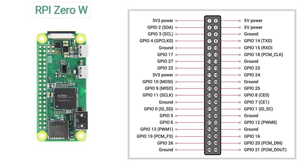
Below is the complete pinout of the Raspberry Pi Zero W, including GPIO pins, power pins, and communication interfaces.
Official Pinout
Power Pins
The GPIO header includes both 3.3V and 5V power outputs that can be used to power small external components.
3.3V Pins
- Pin 1
- Pin 17
These pins supply 3.3V from the onboard voltage regulator and are commonly used for sensors and logic modules.
5V Pins
- Pin 2
- Pin 4
These pins are connected directly to the 5V input rail of the board.
Ground Pins
Ground pins provide the electrical reference for circuits connected to the Raspberry Pi.
Ground pins available on the header:
6, 9, 14, 20, 25, 30, 34, 39
These pins can be used to complete circuits when connecting external devices.
I2C Pins
The I2C interface allows the Raspberry Pi to communicate with many sensors and peripherals using only two wires.
| GPIO | Physical Pin | Function |
|---|---|---|
| GPIO2 | Pin 3 | SDA (Data) |
| GPIO3 | Pin 5 | SCL (Clock) |
SPI Pins
The SPI interface is used for high-speed communication with peripherals such as ADCs, DACs, and display modules.
| GPIO | Pin | Function |
|---|---|---|
| GPIO10 | 19 | MOSI |
| GPIO9 | 21 | MISO |
| GPIO11 | 23 | SCLK |
| GPIO8 | 24 | CE0 |
| GPIO7 | 26 | CE1 |
UART Pins
| GPIO | Pin | Function |
|---|---|---|
| GPIO14 | Pin 8 | TX |
| GPIO15 | Pin 10 | RX |
UART is commonly used for:
- Serial debugging
- GPS modules
- Communication with microcontrollers
PWM Pins
Pulse Width Modulation (PWM) is used for controlling devices such as LED brightness, motors, and servo motors.
PWM-capable pins include:
- GPIO12
- GPIO13
- GPIO18
- GPIO19
Specifications
| Feature | Specification |
|---|---|
| Processor | Broadcom BCM2835 |
| CPU Architecture | ARM1176JZF-S (ARMv6) |
| CPU Clock Speed | 1 GHz |
| GPU | Broadcom VideoCore IV |
| RAM | 512 MB LPDDR2 SDRAM |
| Wireless Connectivity | 2.4 GHz 802.11 b/g/n Wi-Fi |
| Bluetooth | Bluetooth 4.1 + BLE |
| Ethernet | Not available |
| USB Ports | 1 × USB 2.0 (OTG) |
| Power Input | Micro-USB power connector |
| Display Output | Mini HDMI |
| Camera Interface | CSI camera connector |
| GPIO Header | 40-pin GPIO (not pre-soldered) |
| Storage | microSD card slot |
| Video Encoding | H.264 (1080p30) |
| Video Decoding | H.264, MPEG-4 (1080p30) |
| Composite Video | Available via test pads |
| Operating System | Raspberry Pi OS and other Linux distributions |
| Board Dimensions | 65 mm × 30 mm |
Important usage notes
1. USB OTG Port
The Raspberry Pi Zero W includes a USB 2.0 On-The-Go (OTG) port, which allows the board to act either as a USB host or a USB device.
Unlike larger Raspberry Pi boards that have multiple USB ports, the Zero W has only one data USB port.
Common uses include:
- Connecting keyboards, mice, and USB drives
- Interfacing with USB peripherals using an OTG adapter
- Using the board as a USB gadget device (for example, USB Ethernet or USB serial)
To connect standard USB devices, a micro-USB OTG adapter or hub is typically required.
2. Composite video pads (TV Output)
The board also includes composite video output pads, which allow analog video output to older displays or small LCD screens.
These pads are located on the underside of the board.
Typical pins include:
- TV – Composite video signal
- GND – Ground connection
This feature can be useful for:
- Retro gaming projects
- Small embedded displays
- Low-power video applications
Composite video can output standard-definition analog video.
3. RUN pins (Reset function)
The RUN pins provide a simple way to reset the Raspberry Pi without disconnecting power.
Shorting the RUN pins together will restart the board, similar to pressing a reset button on a computer motherboard.
This feature is useful when:
- The system becomes unresponsive
- You want to add a physical reset button to your project enclosure
- Developing embedded systems where easy restart access is needed
The RUN pins are located near the GPIO header on the board.
4. Limited current capability
GPIO pins are intended for signal control, not for powering devices.
- Maximum current per GPIO pin: 16 mA
- Recommended current per pin: 8 mA or less
- Total current across all GPIO pins: about 50 mA
High-power devices such as motors, relays, and large LED arrays should be powered using an external power source and controlled through drivers or transistors.
5. Boot configuration pins
Some GPIO pins are read during the boot process to determine certain startup configurations. Connecting external hardware to these pins may affect how the board boots. If you encounter boot issues, check whether any connected device is interfering with these pins.
6. GPIO header may require soldering
The Raspberry Pi Zero W typically ships with an unsoldered 40-pin GPIO header. To use jumper wires or attach HAT accessories, you may need to solder the header onto the board.
7. Verify pin orientation
Incorrectly identifying the GPIO header orientation can lead to wiring mistakes.
Pin 1 is the 3.3V pin located near the corner of the board, and the odd-numbered pins run along the outer edge of the header. Always double-check the pinout diagram before making connections.
External resources
1. Setup and getting started with Pi Zero W(video tutorial)
2. Comparing Benchmarks of Zero W and 2W