The Raspberry Pi Zero 2 W may be one of the smallest Raspberry Pi boards, but it still exposes the same 40-pin GPIO header used across most Raspberry Pi models. This means the board can work with a wide range of existing sensors, displays, and HAT accessories despite its compact size.
It is built around the Broadcom BCM2710A1 quad-core Cortex-A53 processor running at 1 GHz and includes 512 MB LPDDR2 RAM, making it significantly more powerful than the original Pi Zero while keeping the same compact form factor.
Official Pinout
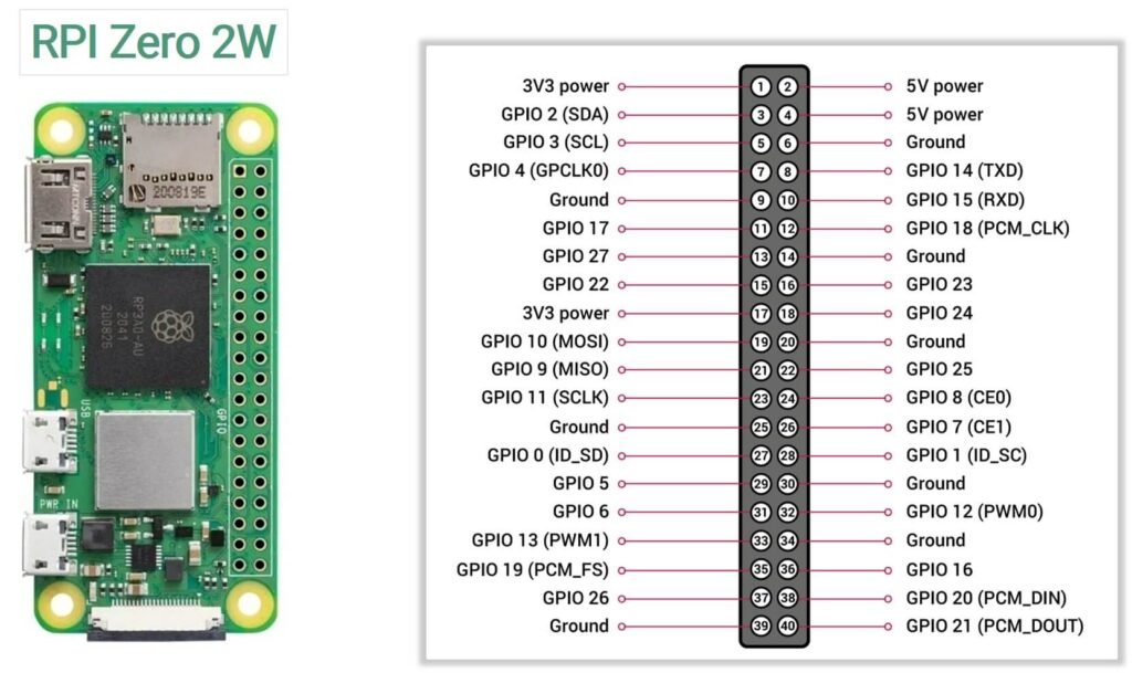
| Pin | Name / Function | Pin | Name / Function |
|---|---|---|---|
| 1 | 3.3V Power | 2 | 5V Power |
| 3 | GPIO2 (SDA1) | 4 | 5V Power |
| 5 | GPIO3 (SCL1) | 6 | Ground |
| 7 | GPIO4 | 8 | GPIO14 (TXD0) |
| 9 | Ground | 10 | GPIO15 (RXD0) |
| 11 | GPIO17 | 12 | GPIO18 (PCM_CLK / PWM0) |
| 13 | GPIO27 | 14 | Ground |
| 15 | GPIO22 | 16 | GPIO23 |
| 17 | 3.3V Power | 18 | GPIO24 |
| 19 | GPIO10 (MOSI) | 20 | Ground |
| 21 | GPIO9 (MISO) | 22 | GPIO25 |
| 23 | GPIO11 (SCLK) | 24 | GPIO8 (CE0) |
| 25 | Ground | 26 | GPIO7 (CE1) |
| 27 | ID_SD (I²C EEPROM) | 28 | ID_SC (I²C EEPROM) |
| 29 | GPIO5 | 30 | Ground |
| 31 | GPIO6 | 32 | GPIO12 (PWM0) |
| 33 | GPIO13 (PWM1) | 34 | Ground |
| 35 | GPIO19 (PCM_FS / SPI1 MISO) | 36 | GPIO16 |
| 37 | GPIO26 | 38 | GPIO20 (PCM_DIN / SPI1 MOSI) |
| 39 | Ground | 40 | GPIO21 (PCM_DOUT / SPI1 SCLK) |
Power Pins
The board provides both 3.3V and 5V power outputs through the header.
3.3V Pins
- Pin 1
- Pin 17
These pins provide 3.3V output from the onboard voltage regulator.
5V Pins
- Pin 2
- Pin 4
These pins are connected directly to the 5V power input of the board.
Ground Pins
The Raspberry Pi Zero 2 W provides multiple ground connections:
Pins: 6, 9, 14, 20, 25, 30, 34, 39
I2C Pins
| GPIO | Physical Pin | Function |
|---|---|---|
| GPIO2 | Pin 3 | SDA |
| GPIO3 | Pin 5 | SCL |
SPI Pins
| GPIO | Pin | Function |
|---|---|---|
| GPIO10 | 19 | MOSI |
| GPIO9 | 21 | MISO |
| GPIO11 | 23 | SCLK |
| GPIO8 | 24 | CE0 |
| GPIO7 | 26 | CE1 |
UART Pins
| GPIO | Pin | Function |
|---|---|---|
| GPIO14 | Pin 8 | TX |
| GPIO15 | Pin 10 | RX |
PWM pins
PWM capable pins include:
- GPIO12
- GPIO13
- GPIO18
- GPIO19
PWM signals allow precise control of analog-like outputs using digital signals.
Pins reserved for HAT EEPROM
Pins 27 and 28 are reserved for identifying HAT (Hardware Attached on Top) modules.
| Physical Pin | GPIO | Function |
|---|---|---|
| 27 | GPIO0 | ID_SD |
| 28 | GPIO1 | ID_SC |
These pins are used for EEPROM communication, allowing the Raspberry Pi to automatically detect compatible add-on boards.
In most projects, these pins are left unused unless working with HAT hardware.
Specifications
| Feature | Specification |
|---|---|
| Processor | Broadcom BCM2710A1 |
| CPU Architecture | Quad-core ARM Cortex-A53 |
| CPU Clock Speed | 1 GHz |
| RAM | 512 MB LPDDR2 SDRAM |
| GPU | Broadcom VideoCore IV |
| Wireless Connectivity | 2.4 GHz 802.11 b/g/n Wi-Fi |
| Bluetooth | Bluetooth 4.2 + BLE |
| Ethernet | Not available |
| USB Ports | 1 × USB 2.0 (OTG) |
| Power Input | Micro-USB power connector |
| Display Output | Mini HDMI |
| Camera Interface | CSI-2 camera connector |
| GPIO Header | 40-pin GPIO (not pre-soldered) |
| Storage | microSD card slot |
| Video Encoding | H.264 (1080p30) |
| Video Decoding | H.264, MPEG-4 (1080p30) |
| Operating System | Raspberry Pi OS and other Linux distributions |
| Board Dimensions | 65 mm × 30 mm |
| Power Consumption | ~0.6 W (idle), higher under load |
Important usage notes
1. GPIO voltage and current limits
GPIO pins on the Raspberry Pi Zero 2 W operate at 3.3V logic levels and are not 5V tolerant.
Important electrical limits:
- GPIO logic voltage: 3.3V
- Maximum current per GPIO pin: 16 mA
- Recommended current per pin: ≤ 8 mA
- Total current across all GPIO pins: ≈ 50 mA
2. BCM vs physical pin numbering
One common point of confusion when working with Raspberry Pi GPIO is the difference between BCM numbering and physical pin numbering.
- Physical numbering refers to the actual pin position on the 40-pin header (1–40).
- BCM numbering refers to the GPIO number assigned by the Broadcom processor.
For example:
| Physical Pin | BCM GPIO |
|---|---|
| 3 | GPIO2 |
| 5 | GPIO3 |
| 8 | GPIO14 |
Most programming libraries use BCM numbering, so it is important to match the correct GPIO number when writing code.
3. Some pins are used during boot
Certain GPIO pins are read during system startup to determine the boot configuration. Connecting components to these pins may affect boot behavior. If possible, avoid using them for critical hardware unless you understand their boot functions.
4. Headers are not always pre-soldered
Most versions of the Raspberry Pi Zero 2 W ship with an unsoldered GPIO header, meaning you may need to solder a 40-pin header before connecting jumper wires or HAT accessories
5. Always check pin orientation
Incorrectly identifying Pin 1 can result in wiring errors that may short power or damage components. Pin 1 is the 3.3V pin located near the corner of the board, and the odd-numbered pins run along the outer edge of the header.
Useful resources
1. Getting started with Raspberry Pi Zero 2W
3. Official datasheet of Pi Zero 2W