Arduino Nano Every is based on the Microchip ATmega4809 running at 20 MHz. It maintains the classic Nano form factor while providing improved performance and additional peripherals.
While the form factor is identical to the original Nano, the internals are significantly upgraded.
- Microcontroller: ATMega4809
- Flash Memory: 48 KB (vs. 32 KB on the Nano)
- SRAM: 6 KB (vs. 2 KB on the Nano)
- Clock Speed: 20 MHz(vs. 16MHz on the Nano)
Official Pinout
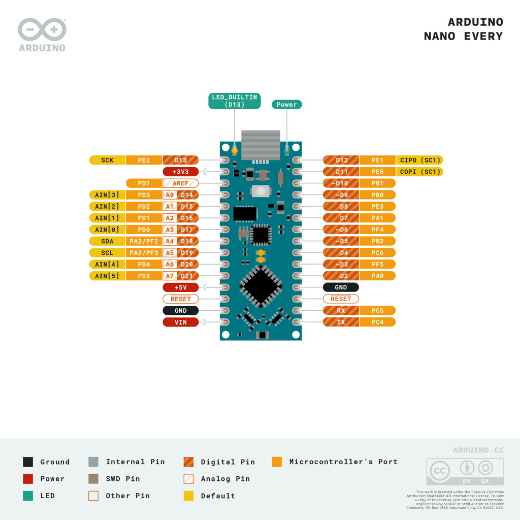
*Img source: official nano every pin mapping pdf
Power Pins
Powering the Nano Every can be done in three ways. Understanding the limits of each is crucial for board longevity.
- VIN: Input voltage pin. You can supply 7V to 21V here. The onboard regulator converts it to 5V.
- 5V: This pin outputs 5V when the board is powered via VIN or USB. It can also be used as an input if you have a regulated 5V source.
- 3V3: Output generated by the internal regulator. Maximum current draw is around 50mA.
- GND: Ground pins (2 total).
Digital and PWM Pins
The board features 20 Digital I/O pins (D0 to D13 and A0 to A5 can also be used as digital pins).
- PWM Pins: Unlike the classic Nano, the Every has 5 PWM pins (D3, D5, D6, D9, and D10). These are used for controlling motor speeds or LED brightness.
- LED_BUILTIN: Internal LED connected to D13.
Analog Input Pins
There are 8 Analog inputs (A0 through A7).
- Resolution: 10-bit (0–1023).
- Note: Pins A6 and A7 are strictly analog inputs and cannot be used as digital I/O.
Communication Interfaces
The Nano Every handles communication slightly differently than the older version because it has more hardware serial ports.
| Interface | Pins | Description |
| UART (Serial) | D0 (RX), D1 (TX) | Used for TTL serial communication. Connected to the USB-to-Serial converter. |
| I2C | A4 (SDA), A5 (SCL) | Used for sensors and displays. Requires pull-up resistors. |
| SPI | D11 (COPI), D12 (CIPO), D13 (SCK) | Controller/Peripheral communication. D10 is typically used for SS (Select). |
Note: The ATMega4809 actually has four hardware UARTS. While the board breaks out one (Serial), you can often access others via multiplexing if you are using the MegaCoreX hardware package.
Specifications
| Feature | Details |
|---|---|
| MCU | ATmega4809 |
| Clock speed | 20 MHz |
| Flash | 48 KB |
| SRAM | 6 KB |
| EEPROM | 256 Bytes |
| Digital I/O pins | 14 |
| PWM pins | 5 |
| Analog inputs | 8 |
| Logic level | 5V |
| USB | Micro-USB |
| Operating voltage | 5V |
Important usage notes
- Every Pin is an Interrupt: Unlike the classic (pins 2 & 3 only), all digital pins can now trigger interrupts.
- 5 PWM pins instead of 6 (D11 is no longer PWM).
- Only 256 bytes available for permanent data storage (the classic had 1024).
- The “Blink” Pin is Different: Pin 13 is still the LED, but it is driven by a different internal port. If you are doing low-level “Port Manipulation” to make the LED blink faster, your old code will not work.
- If you look at the bottom of the board, there are solder jumpers. These allow advanced users to bypass the regulator or change how the USB interacts with the reset pin.
- The Analog-to-Digital converter is much faster.
Helpful resources
1. Introduction to Nano every:
2. Datasheet: download from here
3. Schematics: Official Arduino doc