The STM32 Blue Pill is a low-cost development board based on the STM32F103C8T6 microcontroller. It features a 32-bit Cortex-M3 CPU running up to 72 MHz, operates at 3.3 V logic, and provides a rich set of peripherals, making it suitable for performance-oriented embedded applications.
Pinout
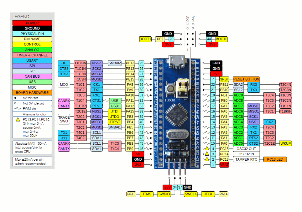
*Image source
S No. Name Pins Description 1 Input / Output Pins PA0–PA15, PB0–PB15, PC13–PC15 Total of 37 GPIO pins available 2 Analog Pins (ADC) PA0–PA7, PB0–PB1 10 analog input pins, 12-bit resolution 3 External Interrupts PA0–PA15, PB0–PB15, PC13–PC15 All GPIOs can be mapped to EXTI interrupt lines 4 PWM Pins PA0–PA3, PA6–PA10, PB0–PB1, PB6–PB9 Up to 15 PWM-capable pins (timer dependent) 5 Serial Communication (USART) USART1: TX/RX – PA9, PA10USART2: TX/RX – PA2, PA3USART3: TX/RX – PB10, PB11 3 hardware USART interfaces 6 SPI SPI1: PA7 (MOSI), PA6 (MISO), PA5 (SCK), PA4 (NSS)SPI2: PB15 (MOSI), PB14 (MISO), PB13 (SCK), PB12 (NSS) 2 SPI peripherals available 7 CAN PA12 (CAN_TX), PA11 (CAN_RX) 1 CAN 2.0B Active interface 8 I2C I2C1: PB7 (SDA), PB6 (SCL) (alt: PB9/PB8) I2C2: PB11 (SDA), PB10 (SCL) 2 I2C channels available 9 Power Pins 3.3V, 5V, GND 3.3V: regulated output5V: USB or external inputGND: ground 10 Onboard LED PC13 Built-in LED (active LOW), usable as GPIO
Specification table
Feature Details MCU STM32F103C8T6 CPU Arm® Cortex®-M3 Max Frequency 72 MHz Flash 64 KB SRAM 20 KB Operating Voltage 2.0 – 3.6 V ADC 2 × 12-bit (up to 16 channels) Timers 7 (incl. advanced motor-control timer) GPIO Up to 37 GPIOs Interrupts 16 EXTI lines Communication I2C ×2, USART ×3, SPI ×2 USB USB 2.0 Full-Speed (device) CAN CAN 2.0B Active Debug SWD, JTAG Low-Power Modes Sleep, Stop, Standby Logic Level 3.3 V
Compatibility
Arduino IDE (STM32 core)
STM32CubeIDE (official)
PlatformIO
ST-Link & SWD programmers
Breadboard-friendly layout
3.3 V logic compatible modules
USB bootloader support (varies by board)
Important Usage Notes
Boot configuration depends on the BOOT0 & BOOT1 pins
GPIOs are not 5V-tolerant (except some 5V-tolerant pins — check datasheet)
PC13 LED is slow due to the internal resistor
SWD pins (PA13, PA14) must remain free for debugging
External crystal improves USB & timing accuracy
Many boards ship with fake STM32 chips (verify before use)
Helpful Resources
Getting started with STM32 Blue Pill(Mini course)