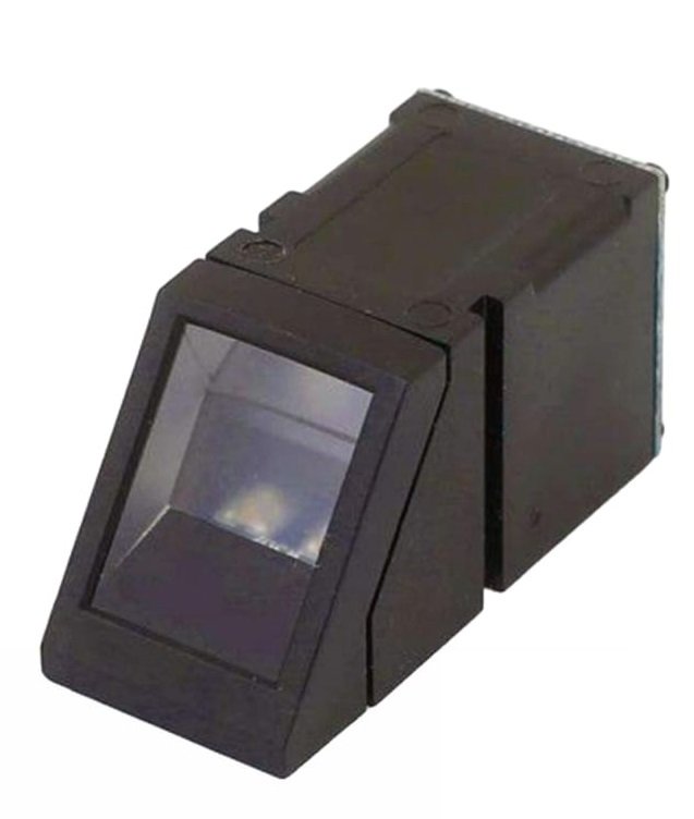
The AS608 is a standalone optical fingerprint sensor module that captures, processes, stores, and matches fingerprints entirely onboard without requiring any external processing. By combining an optical imaging sensor, a DSP processor, a fingerprint alignment algorithm, and onboard Flash memory in a single compact module, it handles all biometric operations independently and communicates results to the host over a simple TTL UART interface.
Pinout
The AS608 connects via an 8-pin JST-style ribbon cable. The connector exposes four functional groups — power, UART serial, touch sense, and USB — across the full 8-pin header.
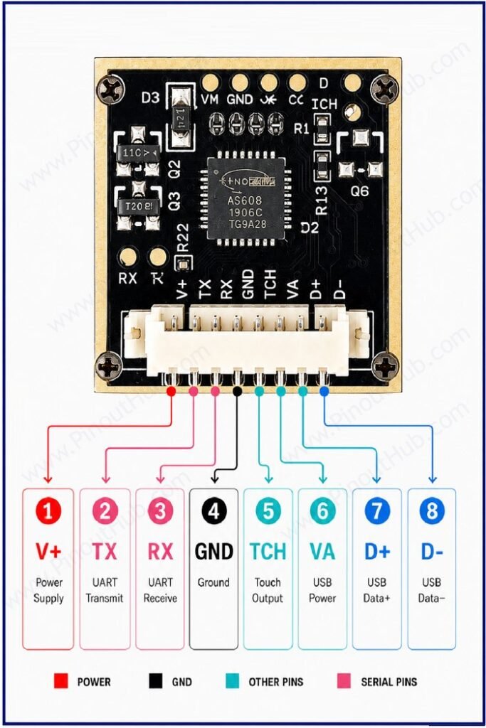
8-pin connector pinout
| Pin | Name | Type | Description |
|---|---|---|---|
| 1 | V+ | Power | Supply input — 3.3V to 6.0V DC; main power supply for the module |
| 2 | TX | Output | UART transmit — connect to microcontroller RXD pin |
| 3 | RX | Input | UART receive — connect to microcontroller TXD pin |
| 4 | GND | Power | Ground |
| 5 | TCH | Output | Touch output — goes active when a finger is detected on the scanning window |
| 6 | VA | Power | USB power — 5V supply for the USB interface |
| 7 | D+ | I/O | USB data positive — connect to host USB D+ for PC communication |
| 8 | D− | I/O | USB data negative — connect to host USB D− for PC communication |
UART connection: TX of the AS608 connects to RXD of the microcontroller; RX of the AS608 connects to TXD — standard cross-connection. Default baud rate is 57600bps.
TCH pin: Goes active when a finger is placed on the glass window. Connect to a GPIO interrupt pin to trigger a scan only on finger detection.
USB pins (VA, D+, D−): Used exclusively for PC communication via USB. Leave unconnected when using the module with a microcontroller over UART.
AS608 Module Construction
Optical Image Sensor An area-array optical sensor beneath the glass scanning window that captures a 500 DPI grayscale image of the fingerprint using Total Internal Reflection. No lens is required between the sensor and the glass — the sensor records a direct contact image of the ridge-valley pattern.
Blue Backlight LED Assembly Blue LEDs inside the module housing that illuminate the finger from below through the glass prism during scanning. Activated only when a scan command is issued — not continuously illuminated during standby. The blue wavelength enhances contrast between ridges and valleys on the optical sensor.
DSP Processor The main processing IC handling all image processing, feature extraction, template generation, template storage management, and fingerprint matching onboard. The host microcontroller never receives raw fingerprint image data during normal operation — only command responses and match results.
Onboard Flash Memory Non-volatile Flash storage holding up to 162 fingerprint templates of 512 bytes each. Templates persist through power cycles and remain until explicitly deleted by UART command.
Red / Green LED Indicators Two onboard LEDs providing visual match feedback. Green illuminates on a successful fingerprint match; red illuminates on a failed match. Both are also controllable via UART command for custom application feedback.
Touch Sense Circuit (6-wire variant) A dedicated circuit connected to TOUCH VCC and TOUCH OUT that detects finger presence on the scanning window surface. Outputs a HIGH signal on TOUCH OUT when a finger is detected, allowing interrupt-driven operation on the host microcontroller.
Specifications
| Parameter | Value |
|---|---|
| Supply | |
| Supply Voltage | 3.3V – 6.0V DC |
| Working Current | 120mA typical |
| Peak Current | 150mA |
| Imaging | |
| Sensor Type | Optical (TIR) |
| Resolution | 500 DPI |
| Scanning Window Area | 14 × 18mm |
| Image Entry Time | < 1.0 second |
| Fingerprint Processing | |
| Characteristic File | 256 bytes |
| Template File | 512 bytes |
| Storage Capacity | Up to 162 templates |
| Matching Modes | 1:1 / 1:N |
| Security Levels | 5 (adjustable) |
| FAR | < 0.001% (level 3) |
| FRR | < 1.0% (level 3) |
| Search Time | < 1.0 second (1:500) |
| Interface | |
| Communication | TTL UART |
| Default Baud Rate | 57600bps |
| Baud Rate Range | 9600 – 115200bps |
| General | |
| LED Indicators | Red (fail) / Green (pass) |
| Operating Temperature | −20°C to +50°C |
| Storage Temperature | −40°C to +85°C |
| Operating Humidity | 40% – 85% RH (non-condensing) |
| Dimensions | 56 × 20 × 21.5mm |
Helpful Resources
- Download the datasheet: here
- AS608 with Arduino
- AS608 with ESP32