The A3144 is a unipolar Hall effect switch — a monolithic integrated circuit that detects the presence of a magnetic field and outputs a digital LOW signal when the south pole of a magnet is brought within range, returning HIGH when the magnet is removed. It combines a Hall effect sensing element, signal conditioning circuitry, and an open-collector output transistor in a single compact three-pin package.
Pinout
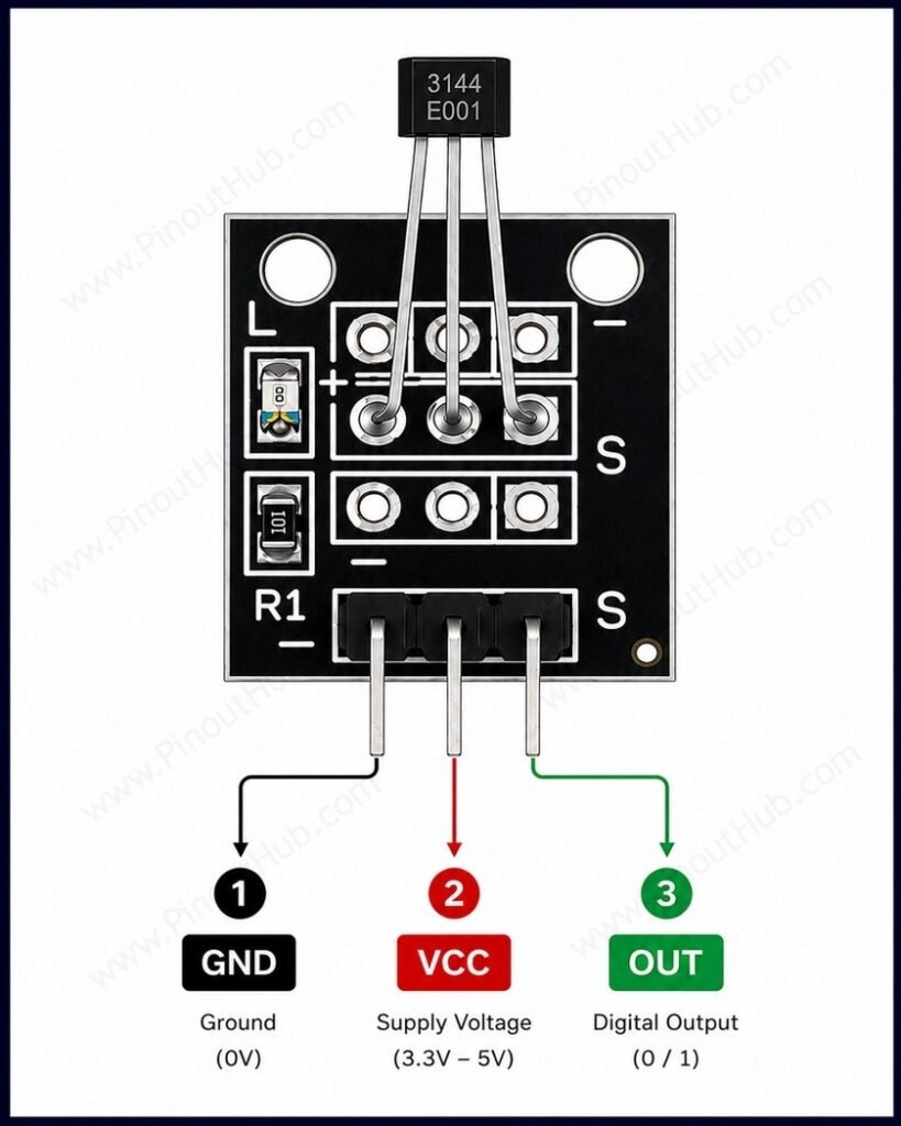
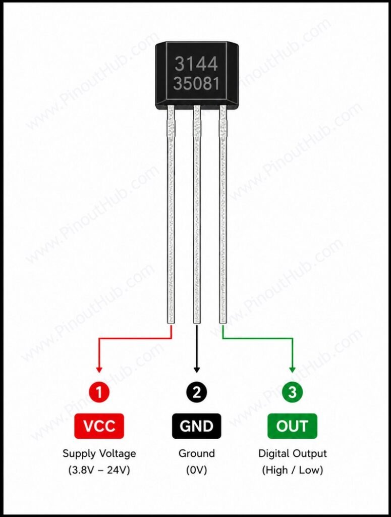
The A3144 is a bare IC available in a 3-pin SIP (single inline package) plastic through-hole package, making it directly breadboard-compatible. The branded face — the flat face with the part number printed on it — must face the magnet for correct operation. Pinout is viewed from the branded face with the leads pointing downward.
3-pin SIP pinout
| Pin | Name | Type | Description |
|---|---|---|---|
| 1 | GND | Power | Ground |
| 2 | Vcc | Power | Supply voltage — connect to 4.5V to 24V DC |
| 3 | OUT | Output | Open-collector digital output — LOW when south pole magnet detected; HIGH (via pull-up) when no field present |
Pull-up resistor: The OUT pin is open-collector and cannot source current. A 10kΩ pull-up resistor between VCC and OUT is required to produce a valid HIGH logic level when no magnet is present. Without it the output floats when inactive and will produce erratic readings on any microcontroller input pin.
Decoupling capacitor: A 0.1µF ceramic capacitor between VCC and GND, placed as close to the VCC pin as possible, is recommended to suppress supply transients that can cause false output transitions.
Orientation: Only the flat branded face is sensitive to magnetic fields. Presenting a magnet to the back or sides of the package will not trigger the output. The south pole of the magnet must face the branded face — north pole presentation produces no response in a unipolar device.
A3144 internal construction
Hall Effect Sensing Element A thin semiconductor element biased by an internal current source. Positioned at the center of the active face of the package. Generates a small transverse Hall voltage when exposed to a perpendicular magnetic field exceeding the operate threshold.
Differential Amplifier Amplifies the weak Hall voltage from the sensing element to a level sufficient to drive the Schmitt trigger comparator. Rejects common-mode noise, improving sensitivity and stability across the operating temperature range.
Schmitt Trigger with Hysteresis Compares the amplified Hall voltage against an internal threshold. The built-in hysteresis band (BOP − BRP, typically 55 Gauss) prevents false switching when the magnetic field is near the trigger level. Drives the output transistor ON when the operate point is exceeded and releases it when the field drops below the release point.
Open-Collector NPN Output Transistor Drives the OUT pin LOW (to near GND) when the Schmitt trigger fires. Rated for 25mA continuous sink current, allowing it to directly drive LEDs, relay coils through a flyback diode, or logic inputs. Cannot source current — a pull-up resistor to VCC is always required.
Voltage Regulator An internal regulator stabilises the bias current to the Hall element and the amplifier supply across the full 4.5V – 24V VCC range, ensuring consistent magnetic switching thresholds regardless of supply voltage variation.
Specifications
| Parameter | Value |
|---|---|
| Supply | |
| Supply Voltage (VCC) | 4.5V – 24V DC |
| Supply Current | 3.5mA typical at 5V |
| Output | |
| Output Type | Open-collector NPN, active LOW |
| Output Sink Current | 25mA continuous |
| Output OFF Voltage | 28V max |
| Output Saturation Voltage | 0.4V at 20mA |
| Magnetic | |
| Active Pole | South only (unipolar) |
| Operate Point BOP (25°C) | 70 Gauss min / 350 Gauss max |
| Release Point BRP (25°C) | 25 Gauss min / 330 Gauss max |
| Hysteresis Bhys (typical) | 55 Gauss |
| Output Behavior | Non-latching |
| General | |
| Operating Temperature (E suffix) | −40°C to +85°C |
| Operating Temperature (L suffix) | −40°C to +150°C |
| Storage Temperature | −65°C to +170°C |
| Package | 3-pin SIP (UA / U) / SOT89 (LT) |
| Status | End of Life — successor: A1104 |
| RoHS | Compliant |
Helpful resources
- Download the datasheet: here
- A3144 with Arduino
- A3144 with ESP32
- A3144 with Raspberry Pi