The YF-S201 is a compact Hall effect water flow sensor that measures liquid flow rate by detecting the rotation of an internal impeller. As water flows through the valve body, it spins the impeller, which carries a small permanent magnet.
Each revolution sweeps the magnet past a sealed Hall effect sensing element, generating a pulse. Pulse frequency is directly proportional to flow rate, allowing any microcontroller to calculate flow rate and cumulative volume by counting pulses over time.
Pinout
The YF-S201 does not use a PCB header — it connects via three color-coded flying leads terminated in bare wire ends or a JST connector depending on the variant. The sensor body has a ½-inch male threaded fitting on each end for inline pipe installation, and a direction arrow molded into the housing that must face the direction of flow.
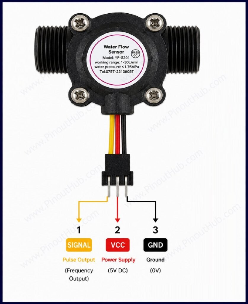
| Wire Color | Name | Type | Description |
|---|---|---|---|
| Red | VCC | Power | Supply voltage — connect to 5V to 18V DC |
| Black | GND | Power | Ground |
| Yellow | SIG | Output | Pulse output — connect to a digital interrupt-capable pin on the microcontroller |
Pull-up resistor: The SIG output is open collector and requires a pull-up resistor to VCC to produce a valid logic level. A 10kΩ resistor between SIG and VCC is the standard recommendation. Some breakout boards and microcontroller boards include internal pull-ups that may be sufficient, but an external 10kΩ pull-up is recommended for reliable operation.
Interrupt pin requirement: Pulse counting must be performed on an interrupt-capable digital input pin. Polling the pin in a loop will miss pulses at higher flow rates, resulting in underreported flow measurements.
Module construction
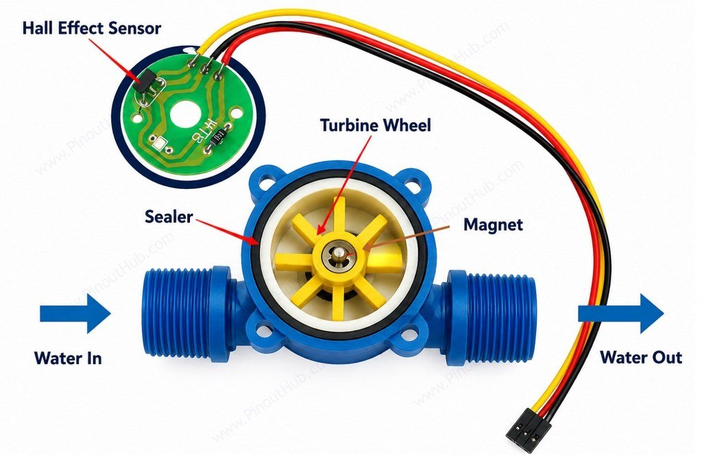
Plastic Valve Body The main housing, molded from food-grade ABS plastic with two ½-inch threaded fittings for inline pipe connection. A flow direction arrow is molded into the body surface and must be aligned with the actual direction of liquid flow during installation.
Impeller Rotor A fan-shaped rotor mounted on a stainless steel bearing inside the flow chamber. Liquid pressure causes it to spin freely. Stainless steel bead bearings at the rotor shaft provide wear resistance and long service life. The impeller has a permanent magnet embedded in its hub.
Permanent Magnet Embedded in the hub of the impeller rotor. As the rotor spins, the magnet rotates with it, generating a continuously alternating magnetic field at the Hall effect sensor location.
Hall Effect Sensing Element Mounted in a sealed enclosure alongside the flow chamber, physically isolated from the liquid by rubber seals. Detects each passage of the rotating magnet and outputs a corresponding voltage pulse on the SIG wire. The sealed isolation ensures the electronics never come into contact with the flowing liquid.
Rubber Seals Upper and lower sealing rings that prevent water ingress into the Hall effect sensor enclosure. These seals also set the maximum allowable working pressure of 1.75 MPa.
Three-Wire Cable Color-coded flying leads — red (VCC), black (GND), and yellow (SIG) — exiting the sensor body. The cable is typically 15–20cm in length.
Specifications
| Parameter | Value |
|---|---|
| Supply | |
| Working Voltage | 4.5V – 24V DC |
| Normal Operating Voltage | 5V – 18V DC |
| Maximum Current | 15mA at 5V |
| Output | |
| Output Type | Digital pulse, open collector |
| Pulse Frequency Factor | ~7.5 Hz per L/min |
| Volume per Pulse | ~2.25mL |
| Flow | |
| Flow Rate Range | 1 – 30 L/min |
| Accuracy | ±10% |
| Maximum Working Pressure | ≤1.75 MPa |
| General | |
| Compatible Liquids | Water and non-corrosive liquids |
| Working Temperature | 0°C – 80°C |
| Working Humidity | 35% – 90% RH non-condensing |
| Pipe Thread | ½ inch |
| Rotor Bearing | Stainless steel |
| Housing Material | ABS plastic (food grade) |
| RoHS | Compliant |
Helpful resources
- Download the datasheet: here
- YF-S201 with Arduino
- YF-S201 with ESP32
- YF-S201 with Raspberry Pi