The rain sensor module is a two-part resistive detection system that senses the presence and intensity of rainfall by measuring the change in electrical conductivity across a set of interleaved nickel-plated copper traces on an exposed sensing board.
As raindrops bridge the traces, resistance drops and the analog output voltage changes proportionally — the wetter the board, the lower the resistance and the higher the output voltage. A separate comparator board converts this analog signal into a threshold-triggered digital output as well.
Pinout
The rain sensor module system has two connectors — a 4-pin header on the comparator board for connection to the microcontroller, and a 2-pin connector where the sensing board cable plugs into the comparator board.
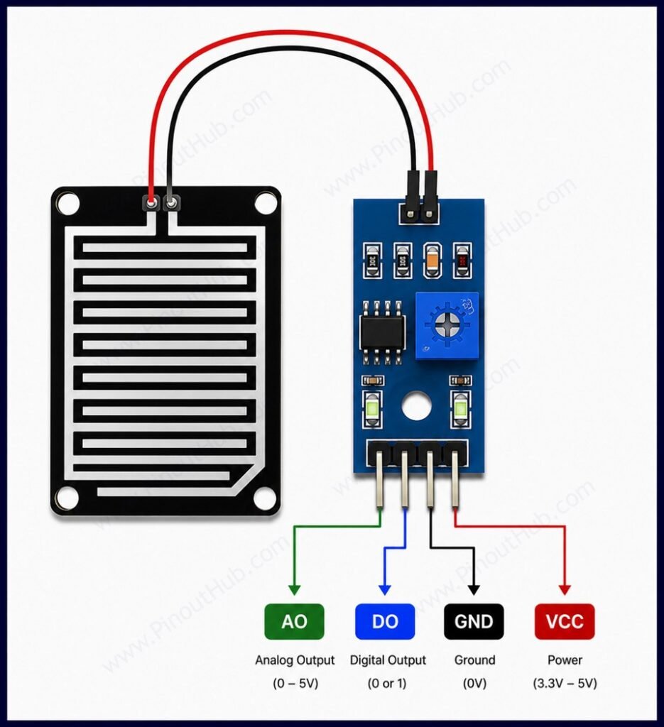
Comparator board pinout (4-pin)
| Pin | Name | Type | Description |
|---|---|---|---|
| 1 | A0 | Output | Analog output — voltage proportional to wetness; connect to a microcontroller ADC input |
| 2 | D0 | Output | Digital output — LOW when rain is detected above the set threshold; HIGH when dry |
| 3 | GND | Power | Ground |
| 4 | VCC | Power | Supply input — 3.3V to 5V |
Sensing board connector (2-pin)
| Pin | Name | Description |
|---|---|---|
| 1 | + | VCC from comparator board |
| 2 | − | Signal / GND return to comparator board |
Digital output logic: The D0 pin is active LOW — it goes LOW when rain is detected and returns HIGH when the surface dries below the threshold. This is the inverse of what some makers expect. The onboard potentiometer on the comparator board sets the switching threshold; rotating it adjusts the reference voltage at the inverting input of the LM393, allowing the trigger point to be tuned for light drizzle or heavy rain.
Module Construction
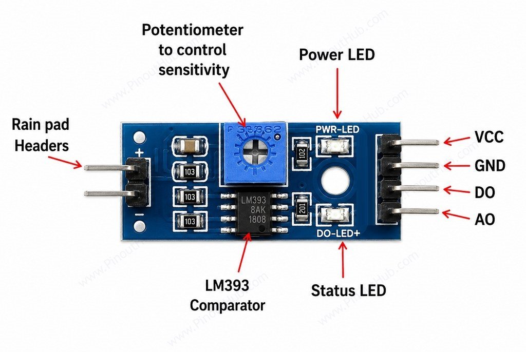
Sensing Board (FC-37 / YL-83) A bare FR4 PCB with two sets of interleaved nickel-plated copper traces across its face. The nickel plating slows oxidation compared to bare copper but does not eliminate it — the traces will corrode over time in continuous wet conditions. Gold-plated sensing boards are available as a more durable alternative.
LM393 Dual Comparator IC The signal processing IC on the comparator board. One comparator channel is used — its non-inverting input receives the analog signal from the sensing board, and its inverting input is connected to the wiper of the potentiometer. The open-collector output drives D0 LOW when the non-inverting input voltage exceeds the reference.
Sensitivity Potentiometer A small trimmer potentiometer on the comparator board that sets the reference voltage on the inverting input of the LM393. Rotating it clockwise or counter-clockwise shifts the switching threshold up or down, adjusting whether the digital output triggers on light or heavy rainfall.
Power Indicator LED Illuminates whenever VCC is applied to the comparator board. Serves only as a power-on indicator.
Digital Output Indicator LED Connected to the D0 output line. Illuminates when D0 goes LOW, providing a visible confirmation that the rain detection threshold has been crossed.
Decoupling Capacitors Small ceramic capacitors on the VCC line of the comparator board filter high-frequency supply noise, preventing false triggers on the LM393 output.
Specifications
| Parameter | Value |
|---|---|
| Supply Voltage | 3.3V – 5V DC |
| Signal Output Current | 15mA |
| Analog Output (A0) | 0V – VCC, inversely proportional to wetness |
| Digital Output (D0) | Active LOW (LOW = rain detected) |
| Comparator IC | LM393 |
| Sensitivity Adjustment | Onboard potentiometer |
| Power Indicator LED | Yes |
| Digital Output LED | Yes |
| Sensing Board Finish | Nickel-plated copper traces |
| Sensing Board Dimensions | 54 × 40mm (typical) |
| Comparator Board Dimensions | 30 × 16mm (typical) |
| Compatible Boards | Arduino, ESP32, Raspberry Pi |
Helpful resources
- Download the datasheet: here
- Rain Sensor Module with Arduino
- Rain Sensor Module with ESP32
- Rain Sensor Module with Raspberry pi pico