The ML8511 is a single-chip UV sensor designed for acquiring UV intensity both indoors and outdoors. The IC integrates a photodiode sensitive to UVA and UVB wavelengths, an internal operational amplifier that converts the photodiode’s photocurrent into a proportional output voltage, and an internal reference voltage circuit — all inside a compact 12-pin ceramic QFN package measuring 4.0 × 3.7 × 0.73mm.
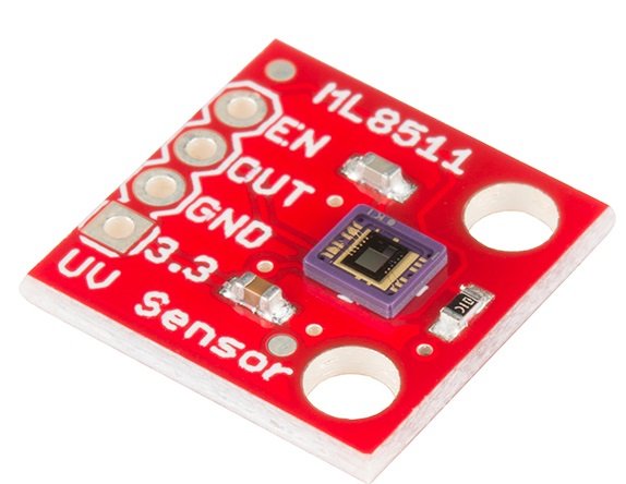
Unlike I²C-based UV sensors that require a microcontroller to initiate readings over a serial bus, the ML8511 produces a continuous analog voltage output with no communication protocol required. The output voltage rises linearly with increasing UV intensity and can be read directly by connecting the OUT pin to any ADC input. No UV light produces approximately 1V at the output; maximum UV intensity produces approximately 2.8V, corresponding to 15 mW/cm².
Pinout
The bare ML8511 IC is a 12-pin ceramic QFN package and is not breadboard-compatible. It is used on a breakout module in virtually all maker applications. Most breakout modules expose five pins through a header.
Breakout module pinout (5-pin)
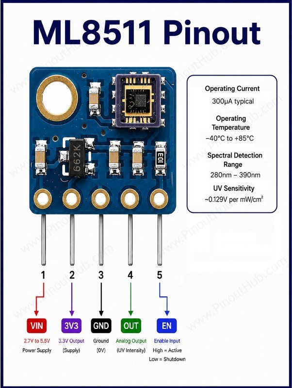
| Pin | Name | Type | Description |
|---|---|---|---|
| 1 | VIN | Power | Power supply input — 3.3V to 5V |
| 2 | 3.3V | Output | Regulated 3.3V output — use as ADC reference on the host microcontroller |
| 3 | GND | Power | Ground |
| 4 | OUT | Output | Analog voltage output proportional to UV intensity |
| 5 | EN | Input | Enable — active HIGH; tie to VIN for always-on operation |
Note: When using the ML8511 with a 5V microcontroller such as an Arduino Uno, do not use the 5V rail as the ADC reference. Instead, connect the 3.3V pin of the breakout board to a spare ADC input on the microcontroller. In firmware, divide the OUT reading by the 3.3V reference reading and multiply by 3.3 to obtain the true output voltage regardless of VCC variation. This approach compensates for USB power supply tolerances and significantly improves measurement accuracy.
ML8511 module construction
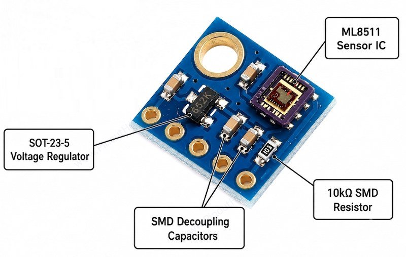
ML8511 Sensor IC The purple ceramic QFN package in the top-left corner of the board. Contains the UV-sensitive photodiode, internal operational amplifier, and internal reference voltage circuit all in a single 4.0 × 3.7 × 0.73mm package.
SOT-23-5 Voltage Regulator / Protection Component The small two-terminal SMD component on the right side of the board. Provides reverse polarity protection or voltage regulation on the supply rail to protect the ML8511 IC from incorrect wiring.
SMD Decoupling Capacitors Multiple small ceramic capacitors placed around the IC on the VDD and internal reference pins, suppressing high-frequency supply noise that would otherwise corrupt the analog output reading.
Bulk Filter Capacitor The larger gold SMD capacitor pad on the bottom-left of the board. Provides low-frequency supply stabilisation, smoothing out slow voltage variations on the power rail.
Bare Through-hole Pads Four unpopulated pads along the top edge for the VIN, EN, OUT, GND, and 3.3V connections. Pin headers must be soldered by the user before use.
Specifications
| Parameter | Value |
|---|---|
| Supply | |
| Supply Voltage (VDD, IC) | 2.7V – 3.6V |
| Supply Voltage (VIN, module) | 3.3V – 5V |
| Operating Current | 300µA typical |
| Standby Current (EN = LOW) | 0.1µA typical |
| Sensing | |
| Detection Type | UVA + UVB |
| Spectral Detection Range | 280nm – 390nm |
| Output | |
| Output Type | Analog voltage |
| Output Voltage (no UV) | ~1.0V typical |
| Output Voltage (~15 mW/cm²) | ~2.8V typical |
| UV Sensitivity | ~0.129V per mW/cm² |
| Output Settle Time | 1ms after EN goes HIGH |
| Control | |
| Enable Pin (EN) | Active HIGH |
| General | |
| Operating Temperature | −40°C to +85°C |
| Package | 12-pin ceramic QFN, 4.0 × 3.7 × 0.73mm |
| RoHS | Compliant |
Helpful Resources
- Download the datasheet: here
- ML8511 with Arduino
- ML8511 with ESP32