The MPU9250 is a 9-axis inertial measurement unit (IMU) that combines a 3-axis gyroscope, a 3-axis accelerometer, and a 3-axis magnetometer in a single compact package. By measuring rotational movement, acceleration, and magnetic field direction, it can provide accurate motion tracking, orientation sensing, and heading information.
This makes the MPU9250 ideal for applications that require full 9-degrees-of-freedom (9-DOF) motion sensing, such as drones, robotics, wearable devices, virtual reality systems, navigation equipment, and attitude and heading reference systems. Its compact size, low power consumption, and high-performance sensor fusion capabilities have made it a popular choice for embedded and IoT projects.
What is MPU9250?
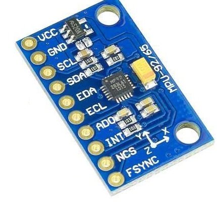
The MPU9250 is constructed as a multi-chip module (MCM), consisting of two separate silicon dies fused into one 3×3×1mm QFN package. One die handles the 3-axis gyroscope and the 3-axis accelerometer, while the other houses the AK8963 3-axis magnetometer.
With its dedicated I2C sensor bus, the MPU9250 directly provides complete 9-axis MotionFusion output. The DMP handles sensor fusion internally — combining gyroscope, accelerometer, and magnetometer data into quaternions or Euler angles — and passes the result to the host over a single I2C or SPI connection. The host processor receives finished orientation data without having to run any fusion algorithm itself.
Watch out for fakes: When buying one of these devices, you may receive a counterfeit — typically the seller sends an MPU6050 instead of an MPU9250. Check the WHO_AM_I register: a genuine MPU9250 returns 0x71, while an MPU6050 returns 0x68.
MPU9250 overview
| Parameter | Value |
|---|---|
| Sensor Type | 9-Axis IMU (Gyroscope + Accelerometer + Magnetometer) |
| Supply Voltage (VDD) | 2.4V – 3.6V |
| Logic Level (VDDIO) | 1.71V – VDD |
| Gyroscope Range | ±250, ±500, ±1000, ±2000 °/s |
| Accelerometer Range | ±2g, ±4g, ±8g, ±16g |
| Magnetometer Range | ±4800 µT |
| ADC Resolution | 16-bit (all three sensors) |
| Output Type | Digital |
| Communication | I²C (400kHz) / SPI (1MHz; 20MHz for registers) |
| I²C Address (MPU) | 0x68 (AD0 → GND) or 0x69 (AD0 → VDD) |
| I²C Address (AK8963) | 0x0C (internal, accessed via MPU9250) |
| Onboard DMP | Yes |
| Temperature Sensor | Yes (onboard) |
| FIFO Buffer | 512 bytes |
| Shock Tolerance | 10,000g |
| Package | 3 × 3 × 1mm QFN (24-pin) |
| Compatible Boards | Arduino Uno, ESP32, Raspberry Pi |
Pinout
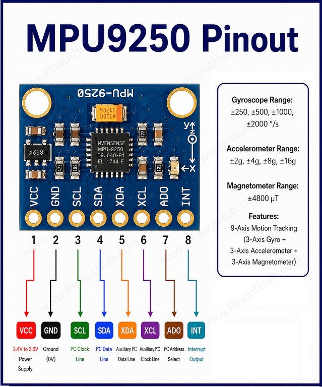
The bare MPU9250 IC is a 24-pin QFN and is not breadboard-compatible. It is used on a breakout module in virtually all maker applications. The breakout module pinout is identical to the MPU6050 module, making it a physical drop-in replacement.
Breakout module pinout (10-pin)
| Pin | Name | Type | Description |
|---|---|---|---|
| 1 | VCC | Power | Module supply — 3.3V or 5V (onboard regulator on most modules) |
| 2 | GND | Power | Ground |
| 3 | SCL | Input | I²C clock / SPI clock (SCK) |
| 4 | SDA | I/O | I²C data / SPI data in (MOSI) |
| 5 | EDA | I/O | Auxiliary I²C data — for external sensors |
| 6 | ECL | Input | Auxiliary I²C clock — for external sensors |
| 7 | AD0 | Input | I²C address select / SPI data out (MISO) |
| 8 | INT | Output | Interrupt output — HIGH when data ready or threshold triggered |
| 9 | NCS | Input | SPI chip select — active LOW |
| 10 | FSYNC | Input | Frame synchronisation input — leave floating if unused |
I²C address: AD0 connected to GND sets the MPU9250 address to 0x68; connected to VDD sets it to 0x69. The AK8963 magnetometer behaves like a separate device with its own I²C address (0x0C) and its own registers. It is not directly accessible — it is controlled via an internal I²C subnet managed by the MPU9250. A standard I²C scanner will only detect the MPU9250 address, not the magnetometer’s.
Working principle
The MPU9250 contains three independent MEMS sensing systems — gyroscope, accelerometer, and magnetometer — all feeding into dedicated 16-bit ADCs and a shared DMP.
Gyroscope Features a user-programmable full-scale range of ±250, ±500, ±1000, or ±2000 °/s with sensitivity scale factors of 131, 65.5, 32.8, or 16.4 LSB/°/s respectively, a noise spectral density of 0.01 °/s/√Hz, and a maximum sample rate of 8000Hz. Measures angular rate around each axis — how fast the device is rotating. Integrating this over time yields angular position but accumulates drift without correction from the accelerometer and magnetometer.
Accelerometer Features a user-programmable full-scale range of ±2g, ±4g, ±8g, or ±16g with sensitivity scale factors of 16384, 8192, 4096, or 2048 LSB/g respectively, a noise spectral density of 300 µg/√Hz, and a maximum sample rate of 4000Hz. Measures linear acceleration along each axis including gravity. Used to determine tilt angle and correct long-term gyroscope drift.
Magnetometer (AK8963) The AK8963 uses highly sensitive Hall-effect sensor technology to detect magnetic fields. It features a full-scale measurement range of ±4800µT, an output data resolution of 0.6µT/LSB (14-bit mode), and a normal operating current of approximately 280µA. Measures the Earth’s magnetic field to determine absolute heading (compass direction) solving the yaw drift problem that gyroscopes alone cannot correct. Maximum magnetometer sample rate is 8Hz in continuous measurement mode 2 (100Hz in mode 1).
DMP and sensor fusion: The DMP processes complex motion processing algorithms, including sensor fusion combining data from all three sensors to get a complete picture of orientation, and low-power functions such as gesture recognition and pedometry. Output can be delivered as raw sensor values, rotation matrices, quaternions, or Euler angles selectable via register configuration.
MPU9250 module construction
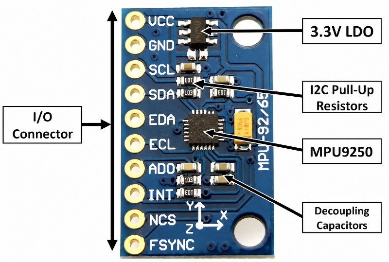
MPU9250 Sensor IC A multi-chip module consisting of two dies in a 3×3×1mm QFN package. One die houses the gyroscope and accelerometer; the other houses the AK8963 magnetometer. All 9 sensing axes, their 16-bit ADCs, the DMP, FIFO buffer, temperature sensor, and both I²C and SPI interface logic are contained within this single package.
3.3V Voltage Regulator Most breakout modules include an onboard LDO that accepts 5V and steps it down to the 3.3V the MPU9250 IC requires, allowing direct connection to an Arduino 5V pin. If powering from 3.3V directly, the solder jumper near the onboard regulator can be bridged to bypass it.
Pull-up Resistors Onboard pull-up resistors on the SDA, SCL, and nCS lines hold them at a high logic level when idle, as required by the I²C and SPI protocols. No external resistors are needed for standard operation.
Pull-down Resistors Onboard pull-down resistors on the FSYNC and AD0 lines set their default states — AD0 pulled low sets the default I²C address to 0x68; FSYNC pulled low disables frame sync by default. Both can be overridden externally.
Decoupling Capacitors Filter high-frequency noise on the VDD and VDDIO supply rails. The MPU9250’s internal oscillator accuracy of ±1% over temperature depends on clean power — supply noise shows up directly as timing jitter, which affects the accuracy of integrated angle calculations.
Specifications
The detailed specifications are listed below.
| Parameter | Value |
|---|---|
| Supply Voltage (VDD) | 2.4V – 3.6V |
| Logic Voltage (VDDIO) | 1.71V – VDD |
| Normal Operating Current | 3.5mA (all sensors active) |
| Sleep Current | 8µA |
| Low-Power Accel (0.98Hz) | 8.4µA |
| Low-Power Accel (31.25Hz) | 19.8µA |
| Magnetometer Current | 280µA (normal mode) |
| Gyroscope | |
| Full-Scale Range | ±250 / ±500 / ±1000 / ±2000 °/s |
| Sensitivity (±250°/s) | 131 LSB/°/s |
| Sensitivity (±2000°/s) | 16.4 LSB/°/s |
| ADC Resolution | 16-bit |
| Noise Spectral Density | 0.01 °/s/√Hz |
| Sample Rate | Up to 8000Hz |
| Accelerometer | |
| Full-Scale Range | ±2g / ±4g / ±8g / ±16g |
| Sensitivity (±2g) | 16384 LSB/g |
| Sensitivity (±16g) | 2048 LSB/g |
| ADC Resolution | 16-bit |
| Noise Spectral Density | 300 µg/√Hz |
| Sample Rate | Up to 4000Hz |
| Magnetometer (AK8963) | |
| Full-Scale Range | ±4800 µT |
| Resolution | 0.6 µT/LSB (14-bit mode) |
| ADC Resolution | 14-bit / 16-bit (selectable) |
| Sample Rate | Up to 8Hz (mode 2) / 100Hz (mode 1) |
| I²C Address | 0x0C (internal) |
| General | |
| Temperature Range | −40°C to +85°C |
| Temperature Sensitivity | 333.87 LSB/°C |
| I²C Speed | Up to 400kHz |
| SPI Speed | Up to 1MHz (20MHz for sensor registers) |
| MPU I²C Address | 0x68 (AD0 = 0) / 0x69 (AD0 = 1) |
| WHO_AM_I Register | 0x71 |
| FIFO Buffer | 512 bytes |
| DMP | Yes (MotionFusion, gesture, pedometer) |
| Shock Tolerance | 10,000g |
| Package | 24-pin QFN |
| Dimensions | 3 × 3 × 1mm |
| Status | End of Life (EoL)-successor: ICM-20948 |
| RoHS | Compliant |
Helpful resouces
- Download the datasheet: here
- MPU9250 with Arduino
- MPU9250 with ESP32
- MPU9250 with Raspberry Pi