The ESP32 Dev Kit C V1 is a Wi-Fi and Bluetooth–enabled microcontroller development board based on the ESP32 SoC from Espressif Systems. It integrates a dual-core 32-bit Tensilica Xtensa LX6 processor, operating up to 240 MHz, and is designed for IoT, wireless communication, and real-time embedded applications.
Pinout
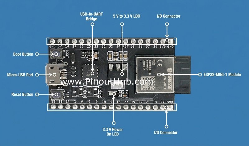
There are three popular variants of this board based on the number of pins exposed: 30 pins, 36 pins, and 38 pins.
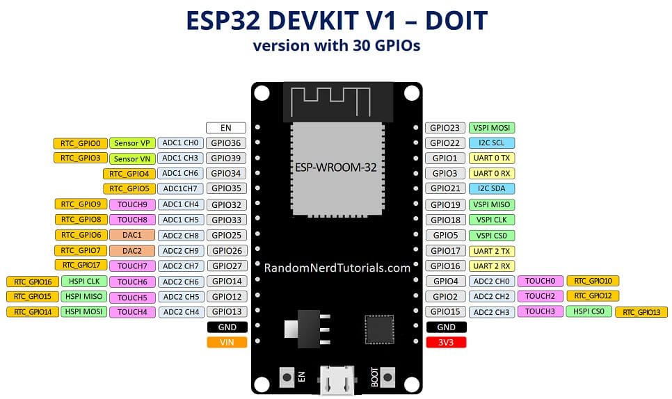
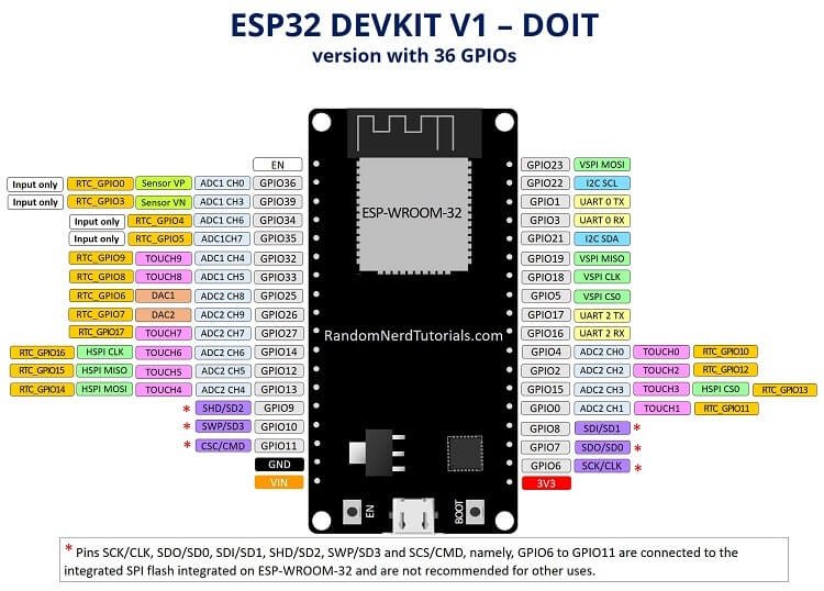
*The above two image source
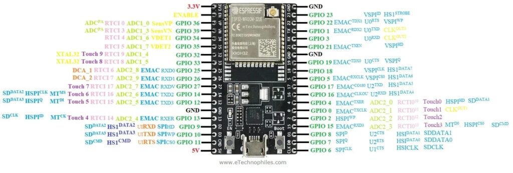
*38-pin variant pinout image source
| GPIO | Type | ADC | Special Notes / Default Functions | Safe to Use? |
|---|---|---|---|---|
| VIN | Power | — | 5V input from external supply | — |
| 5V | Power | — | 5V from USB | — |
| 3V3 | Power | — | Regulated 3.3V output | — |
| GND | Power | — | Ground | — |
| EN | Control | — | Reset/Chip enable (LOW = reset) | — |
| GPIO0 | Digital | ADC2_CH1 | Boot pin (LOW = flashing mode) | Careful |
| GPIO1 | Digital | — | UART0 TX (programming/logs) | Avoid if using Serial |
| GPIO2 | Digital | ADC2_CH2 | Boot strapping pin | Careful |
| GPIO3 | Digital | — | UART0 RX | Avoid if using Serial |
| GPIO4 | Digital | ADC2_CH0 | — | Yes |
| GPIO5 | Digital | — | Default SPI CS, boot strapping | Yes |
| GPIO6 | — | — | Connected to SPI flash | No |
| GPIO7 | — | — | Connected to SPI flash | No |
| GPIO8 | — | — | Connected to SPI flash | No |
| GPIO9 | — | — | Connected to SPI flash | No |
| GPIO10 | — | — | Connected to SPI flash | No |
| GPIO11 | — | — | Connected to SPI flash | No |
| GPIO12 | Digital | ADC2_CH5 | Boot strapping (flash voltage) | Risky |
| GPIO13 | Digital | ADC2_CH4 | — | Yes |
| GPIO14 | Digital | ADC2_CH6 | Default SPI CLK | Yes |
| GPIO15 | Digital | ADC2_CH3 | Boot strapping | Careful |
| GPIO16 | Digital | — | UART2 RX | Yes |
| GPIO17 | Digital | — | UART2 TX | Yes |
| GPIO18 | Digital | — | SPI SCK | Yes |
| GPIO19 | Digital | — | SPI MISO | Yes |
| GPIO21 | Digital | — | Default I2C SDA | Yes |
| GPIO22 | Digital | — | Default I2C SCL | Yes |
| GPIO23 | Digital | — | SPI MOSI | Yes |
| GPIO25 | Digital | ADC2_CH8 | DAC1 | Yes |
| GPIO26 | Digital | ADC2_CH9 | DAC2 | Yes |
| GPIO27 | Digital | ADC2_CH7 | — | Yes |
| GPIO32 | Digital | ADC1_CH4 | — | Yes |
| GPIO33 | Digital | ADC1_CH5 | — | Yes |
| GPIO34 | Input only | ADC1_CH6 | No output capability | Input only |
| GPIO35 | Input only | ADC1_CH7 | No output capability | Input only |
| GPIO36 (VP) | Input only | ADC1_CH0 | No output capability | Input only |
| GPIO39 (VN) | Input only | ADC1_CH3 | No output capability | Input only |
- *GPIO: Please check your variant pin mapping before referring to the table above. For example, 30 pin variant doesn’t have GPIO pins 0,6,7,8,9,10,11 exposed
Pin functions
- GPIO36–39 → Input-only ADC pins
- GPIO34–39 → No internal pull-up/down resistors
- GPIO25 & GPIO26 → DAC outputs
- GPIO21 (SDA) → Default I2C data
- GPIO22 (SCL) → Default I2C clock
- GPIO23 (MOSI) → SPI MOSI
- GPIO19 (MISO) → SPI MISO
- GPIO18 (SCLK) → SPI clock
- GPIO5 → SPI CS (commonly used)
- EN → Chip enable/reset
- VIN → 5V input when not USB powered
- 3V3 → Regulated 3.3V output
Specifications
| Feature | Details |
|---|---|
| SoC | Espressif ESP32 |
| CPU | Dual-core Xtensa LX6 (up to 240 MHz) |
| Wi-Fi | 802.11 b/g/n |
| Bluetooth | Classic + BLE |
| Flash | Typically 4 MB |
| GPIO pins | Up to 30+ exposed |
| ADC | 18 channels (12-bit) |
| DAC | 2 channels |
| Logic level | 3.3V |
| Operating voltage | 3.0–3.6V |
| Power input | 5V via Micro-USB or VIN |
Compatibility
- Variants with 30, 36 or 38 pins exposed
- Boards with different USB connectors are available (Micro-USB vs USB-C)
- Arduino IDE, MicroPython compatible
- Supports ESP-IDF (official SDK)
- Breadboard-friendly form factor
- 3.3V logic level
- Wi-Fi + Bluetooth onboard
- Touch-sensing GPIOs
- Some pins are restricted during boot
Important usage notes
- GPIOs operate at 3.3V only and are not 5V tolerant
- GPIO6–11 are connected to the onboard flash and should not be used
- Some pins affect boot mode:
- GPIO0, GPIO2, GPIO12, and GPIO15 must be in the correct states during boot
- GPIO34–39 are input-only pins
- ADC2 pins cannot be used while Wi-Fi is active
- Avoid drawing high current from the 3.3V pin
Helpful Resources
- Introduction to ESP32 DevKit V1:
- Official Documentation: Schematics and in-depth info