The Arduino Nano is a small form factor dev board based on the ATmega328P 8-bit AVR architecture, offering the same core processing capabilities and peripheral features as the Arduino Uno. It provides 22 digital I/O pins and 8 analog input channels.
This page presents the complete Arduino Nano pinout, covering digital and analog pin mapping, power pins, communication interfaces (UART, I2C, SPI), PWM support, and current limitations.
Official Pinout
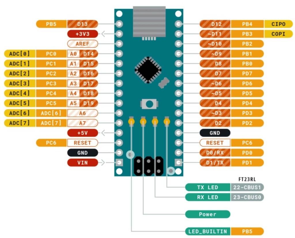
Source: Nano Pin diagram pdf
| Feature | Count |
|---|---|
| Digital I/O pins | 14 |
| PWM pins | 6 |
| Analog input pins | 8 |
| UART | 1 |
| I2C | 1 |
| SPI | 1 |
| 5V pins | 1 |
| 3.3V pins | 1 |
| Ground pins | 2 |
| Max current per I/O pin | 20 mA (recommended) |
Pin Function
- D0 (RX) → UART receive pin (serial communication)
- D1 (TX) → UART transmit pin
- D2–D13 → Digital input/output pins
- PWM pins (3, 5, 6, 9, 10, 11) → PWM output for LED dimming and motor control
- A0–A7 → Analog input pins (10-bit ADC)
- A4 (SDA) → I2C data line
- A5 (SCL) → I2C clock line
- D10 (SS) → SPI slave select
- D11 (MOSI) → SPI master-out slave-in
- D12 (MISO) → SPI master-in slave-out
- D13 (SCK) → SPI clock and onboard LED
- VIN → External power input (7–12V recommended)
- 5V → Regulated 5V output
- 3.3V → 3.3V output (low current)
- GND → Ground reference
- RESET → Resets the microcontroller
Important usage notes
- Avoid using D0 and D1 while uploading code or using the Serial Monitor
- Each GPIO pin should source or sink no more than 20 mA(recommended). Maximum is 40 mA
- Can be powered via:
- USB Mini-B (5V)
- VIN pin (7–12V recommended)
- 5V pin (regulated external supply)
- The 3.3V pin provides limited current and should not power external modules with high demand
Compatibility
- 5V logic level
- Supports I2C, SPI, and UART
- Fully breadboard-friendly
- USB-powered (Mini-USB)
- Same core MCU as Arduino Uno
Helpful Resources
- Download datasheet: Official Arduino Nano documentation
- Reference schematic: Arduino Nano R3 schematic (PDF)
- Want to know when to use an Arduino Nano board? Check the video below: