Arduino Uno, introduced in 2010, is built around the ATmega328P microcontroller and provides 14 digital I/O pins, 6 analog inputs, and standard UART, I2C, and SPI interfaces at 5V logic level.
This page provides the complete Arduino Uno pinout, including digital and analog pin mapping, power rails, communication interfaces (UART, I2C, SPI), and current limitations.
Official Pinout
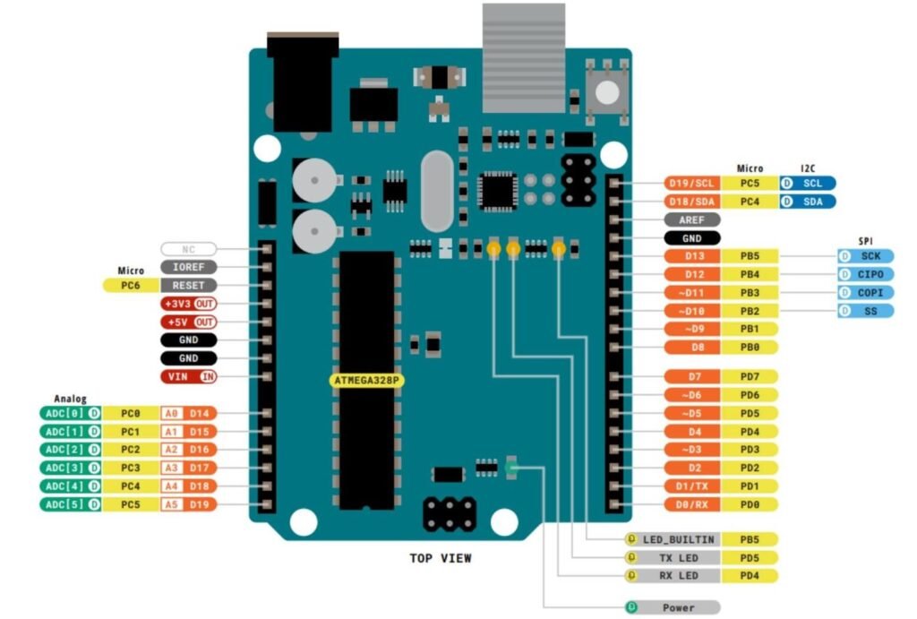
Source: Arduino pinout pdf
Pinout at a glance
| Feature | Count |
|---|---|
| Digital I/O pins | 14 |
| PWM pins | 6 |
| Analog input pins | 6 |
| UART | 1 |
| I2C | 1 |
| SPI | 1 |
| 5V pins | 1 |
| 3.3V pins | 1 |
| Ground pins | 3 |
| Max current per I/O pin | 20 mA (recommended) |
Pin function
- D0 (RX) → UART receive pin (used for serial communication)
- D1 (TX) → UART transmit pin
- D2–D13 → Digital input/output pins
- PWM pins (3, 5, 6, 9, 10, 11) → Used for LED dimming, motor speed control
- A0–A5 → Analog input pins (10-bit ADC)
- A4 (SDA) → I2C data line
- A5 (SCL) → I2C clock line
- D10 (SS) → SPI slave select
- D11 (MOSI) → SPI master-out slave-in
- D12 (MISO) → SPI master-in slave-out
- D13 (SCK) → SPI clock and onboard LED
- VIN → External power input (recommended 7–12V)
- 5V → Regulated 5V output
- 3.3V → 3.3V output (low current)
- GND → Ground reference
Important usage notes
- Avoid using D0 and D1 when uploading code or using the Serial Monitor
- Each I/O pin should source or sink no more than 20 mA
- Do NOT power motors, relays, or high-current devices directly from GPIO pins
- Can be powered via USB (5V), the DC barrel jack (7-12V recommended), or the VIN pin (7-20V)
- When using external power, connect it through VIN or the barrel jack
Compatibility
- 5V logic level
- Supports I2C, SPI & UART
- Not breadboard-friendly
- USB-B powered
- Limited current per pin
Helpful resources
- Download datasheet: Official Arduino Uno documentation
- Reference schematic: Arduino Uno R3 schematic (PDF)
- Beginner tutorials: Free video course