The water level sensor is a low-cost resistive immersion sensor that detects water presence and depth by measuring the change in electrical conductivity across a set of interleaved exposed copper traces. The traces act as a variable resistor — in air, resistance between them is effectively infinite; as water bridges progressively more trace pairs, resistance drops and the analog output voltage rises in proportion to immersion depth.
Pinout
The water level sensor module has a simple 3-pin header at the top of the board and a bare sensing area at the bottom that is submerged in water during use.
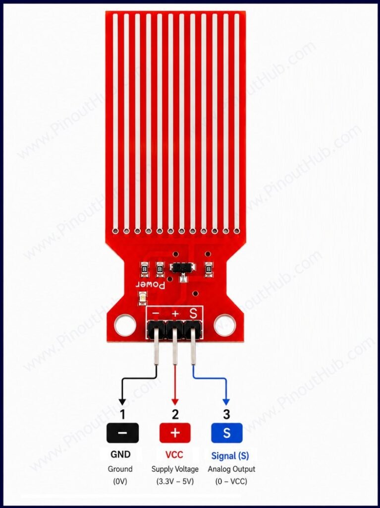
3-pin header pinout
| Pin | Name | Type | Description |
|---|---|---|---|
| 1 | − | Power | Ground |
| 2 | + | Power | VCC supply — connect to 3.3V or 5V; connect to a digital output pin for gated power |
| 3 | S | Output | Analog signal output — connect to an ADC input; voltage rises with increasing water level |
This straightforward three-pin interface outputs a continuous analog signal directly compatible with any microcontroller ADC. While ideal for rapid prototyping in flood detection, automated irrigation, and tank monitoring, continuous submersed operation requires gated power management to prevent trace electrolysis.
Module construction
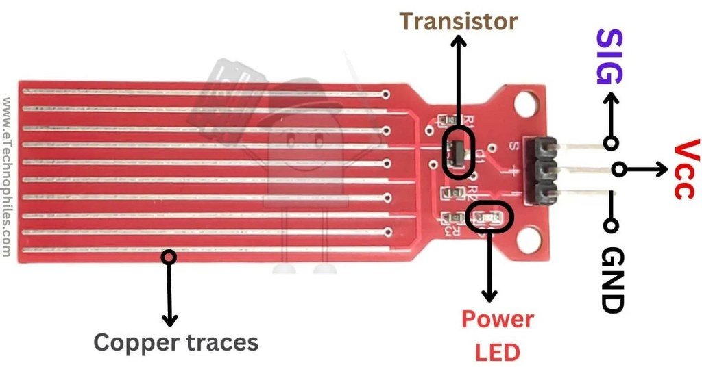
Sensing Traces Ten interleaved copper traces screen-printed and etched onto the FR4 PCB across a 40 × 16mm sensing area. Five traces are power lines connected to VCC; five are sense lines connected to the transistor base. Water bridging the two sets completes the circuit and drives the output.
S8050 NPN Transistor The signal conditioning component. Its base is driven by the sense traces, and its emitter output is connected to the OUT pin through a 100Ω resistor. Acts as a variable amplifier — the more water contact, the more base current, and the higher the output voltage.
100Ω Resistors One resistor limits current through the power traces to protect the sensing surface. A second resistor in the transistor emitter path sets the output voltage swing and protects the OUT pin.
Power Indicator LED A small LED that illuminates whenever VCC is applied to the module. Serves only as a power-on indicator and plays no role in the sensing process.
3-pin Header A standard 2.54mm pitch header exposing the S (signal), + (VCC), and − (GND) connections. No soldering or additional components are required for use.
Specifications
| Parameter | Value |
|---|---|
| Supply Voltage | 3.3V – 5V DC |
| Operating Current | < 20mA |
| Output Type | Analog voltage |
| Output Range | 0V (dry) – ~VCC (fully submerged) |
| Detection Area | 40 × 16mm |
| Transistor | S8050 NPN |
| Working Temperature | −30°C to +50°C |
| Operating Humidity | 10% – 90% non-condensing |
| PCB Material | FR4 double-sided HASL |
| Mounting Hole Diameter | 3mm |
| Dimensions | 65 × 20 × 8mm |
| Weight | ~3g |
Helpful resources
- Download the datasheet: here
- Water Level Sensor with Arduino
- Water Level Sensor with ESP32
- Water Level Sensor with Raspberry Pi