The HC-SR04 is a low-cost ultrasonic distance sensor module that measures distance to an object by emitting a burst of ultrasonic sound waves and timing how long it takes for the echo to return. By using the known speed of sound, the time delay between transmission and reception is converted into an accurate non-contact distance reading.
This makes the HC-SR04 ideal for applications such as obstacle avoidance, robotics, automated parking sensors, liquid level detection, and proximity sensing. Its low cost, simple digital interface, and wide community support have made it one of the most widely used distance sensors in maker and educational projects.
What is HC-SR04?
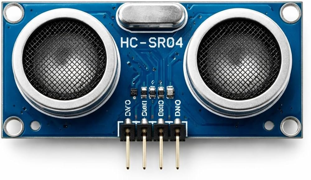
The HC-SR04 is a 4-pin module featuring two round components on its front that resemble eyes — these are the ultrasonic transmitter and receiver. The transmitter emits a short burst of ultrasonic sound waves, which travel through the air, reflect off any object in their path, and return to the receiver as an echo. The onboard circuitry measures the time taken for this round trip and converts it directly into a proportional output pulse on the Echo pin.
Distance is then calculated by the host microcontroller using the standard speed-of-sound formula: distance equals time multiplied by the speed of sound, divided by two to account for the wave traveling out and back. The HC-SR04 operates using ultrasonic frequencies well above the range of human hearing, allowing accurate non-contact distance measurement in everyday environments.
Note on accuracy: Ranging accuracy can reach around 3mm under good conditions, with an effective detection angle of less than 15°. Soft, angled, or sound-absorbing surfaces can reduce accuracy or cause missed echoes, since the sensor relies on a clean reflection returning to the receiver.
HC-SR04 overview
| Parameter | Value |
|---|---|
| Sensor Type | Ultrasonic Distance Sensor |
| Supply Voltage | 5V DC |
| Operating Current | < 15mA |
| Measurement Range | 2cm – 400cm |
| Ranging Accuracy | Up to ±3mm |
| Effective Detection Angle | < 15° |
| Ultrasonic Frequency | 40kHz |
| Trigger Pulse Width | 10µs |
| Output Signal | Echo pulse (TTL), proportional to distance |
| Transducers | 2 (dedicated transmitter + receiver) |
| Compatible Boards | Arduino, ESP32, Raspberry Pi, PIC, ARM |
| Package | Small PCB module, 2 round transducers on front |
Pinout
The HC-SR04 is a simple 4-pin module that ships fully assembled, with two round transducer elements visible on the front face — the larger one is the transmitter, the other is the receiver.
4-pin pinout
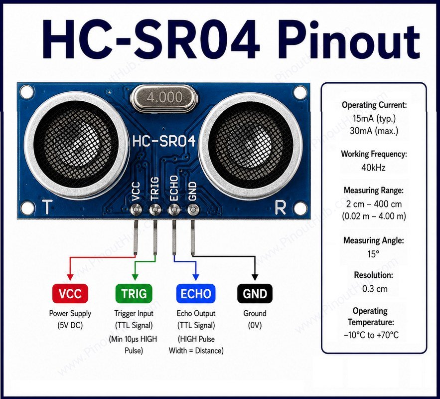
| Pin | Name | Type | Description |
|---|---|---|---|
| 1 | VCC | Power | Power supply — regulated 5V |
| 2 | Trig | Input | Trigger input — pulsed HIGH for 10µs to start a measurement |
| 3 | Echo | Output | Echo output — goes HIGH for a duration proportional to distance measured |
| 4 | GND | Power | Ground connection |
Wiring note: Because the HC-SR04 operates and outputs at 5V logic, its Echo pin should be stepped down (typically via a simple voltage divider) before connecting directly to a 3.3V-only microcontroller input such as on many ESP32 boards, to avoid exceeding the input’s voltage tolerance.
Working principle
The HC-SR04 measures distance using the same echolocation principle bats use to navigate — emit a sound pulse, then measure how long it takes to bounce back. To start a measurement, the Trig pin is held HIGH for at least 10µs. This causes the module to emit a burst of eight ultrasonic pulses at 40kHz from the transmitter.
These pulses travel through the air until they strike an object and reflect back toward the sensor, where the receiver detects the returning echo. The onboard circuitry then drives the Echo pin HIGH for an amount of time exactly equal to the time taken for the ultrasonic wave to travel out and return.
The host microcontroller measures the duration that Echo stays HIGH and calculates distance using: distance = (time × speed of sound) / 2. The speed of sound in air at room conditions is commonly taken as approximately 340m/s for this calculation, with the division by two accounting for the round-trip travel of the sound wave.
Measurement cycle: Successive measurements should be spaced apart to allow any previous echo to fully die out before triggering again, preventing one measurement’s reflections from being mistaken for the next reading’s echo.
HC-SR04 module construction
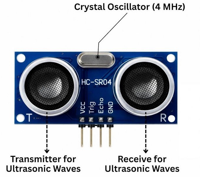
Ultrasonic Transmitter: One of the two circular transducers located on the front of the module. It converts electrical pulses into 40 kHz ultrasonic sound waves and transmits them toward the target object.
Ultrasonic Receiver: The second circular transducer, responsible for detecting the ultrasonic waves reflected back from objects. By using a dedicated receiver, the module can accurately detect echoes while minimizing interference from the transmitted signal.
Control IC: The onboard integrated circuit controls the module’s operation. It generates the ultrasonic burst, processes the received echo signal, and manages the timing required for distance measurement.
Driver Circuit: This circuit provides the electrical excitation needed to drive the ultrasonic transmitter. It ensures that a stable and consistent 40 kHz ultrasonic pulse is generated whenever the module is triggered.
Signal Amplifier and Comparator Circuit: The echo signal received by the ultrasonic receiver is extremely weak. The amplifier boosts the signal strength, while the comparator distinguishes valid echoes from background noise before sending the data to the control IC.
Oscillator: The oscillator generates a stable clock signal for the module’s electronic circuits. This timing reference helps synchronize pulse generation and echo measurement, improving distance measurement accuracy.
Timing Circuit: The timing circuit measures the interval between transmitting an ultrasonic pulse and receiving its echo. This time-of-flight measurement is used to calculate the distance to the target object.
4-Pin header: A simple interface providing access to the module’s four connections: VCC, Trig, Echo, and GND. These pins allow easy integration with microcontrollers, development boards, and breadboards.
Specifications
The key specifications are listed below.
| Parameter | Value |
|---|---|
| Supply Voltage | 5V DC |
| Operating Current | < 15mA |
| Measurement Range | 2cm – 400cm |
| Ranging Accuracy | Up to ±3mm |
| Effective Angle | < 15° |
| Ultrasonic Frequency | 40kHz |
| Trigger Pulse Width | 10µs (active HIGH) |
| Output Signal | TTL Echo pulse, proportional to distance |
| Transducer Count | 2 (separate TX and RX) |
| Logic Level | 5V |
| Package | Small PCB module with 2 transducers |
Helpful Resources
- Download the datasheet: here
- HC-SR04 with Arduino
- HC-SR04 with ESP32
- HC-SR04 with Raspberry Pi