The GP2Y1010AU0F is a compact optical dust sensor manufactured by Sharp that combines an infrared emitting diode and a phototransistor in a single plastic housing. By detecting the intensity of light scattered by airborne particles, it can provide a real-time analog voltage output proportional to dust concentration in the surrounding air.
This makes the GP2Y1010AU0F ideal for applications that require low-cost air quality monitoring, such as air purifiers, air conditioners, vacuum cleaners, HVAC systems, and environmental sensing stations. Its compact size, simple analog interface, and low power consumption have made it a popular choice for embedded and IoT projects.
What is GP2Y1010AU0F?
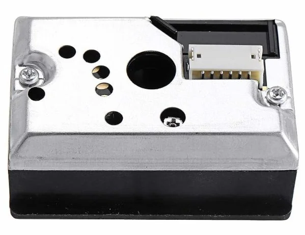
The GP2Y1010AU0F is built around a single plastic sensing chamber containing two optical components — an infrared LED and a phototransistor — arranged diagonally opposite each other. Neither component faces the other directly; instead, both are angled so that their optical axes cross at a point inside the sensing chamber. Only light scattered sideways by dust particles in that crossing zone reaches the phototransistor, which makes the sensor selective to airborne particulate matter rather than ambient light.
An onboard amplifier circuit boosts the weak phototransistor signal into a usable 0–3.4V analog output range. A factory-set sensitivity trimmer (VR) inside the housing calibrates this gain at production — the datasheet explicitly warns never to adjust it, as doing so invalidates the electro-optical specifications.
GP2Y1010AU0F overview
| Parameter | Value |
|---|---|
| Sensor Type | Optical Dust / Air Quality Sensor |
| Supply Voltage (VCC) | 4.5V – 5.5V |
| Output Type | Analog Voltage |
| Sensitivity | 0.5V / (0.1 mg/m³) typical |
| Output Voltage (no dust, Voc) | 0.9V typical |
| Output Voltage High (VOH) | 3.4V typical |
| LED Drive Current | 11mA typical / 20mA max |
| Consumption Current | 20mA max |
| LED Pulse Cycle | 10ms |
| LED Pulse Width | 0.32ms |
| Dust concentration range | 0 to 0.5mg/m3 |
| Operating Temperature | −10°C to +65°C |
| Detection Target | Dust, smoke, fine particulate matter |
| Compatible Boards | Arduino Uno, ESP32, Raspberry Pi |
| Package | Plastic housing with 6-pin JST connector |
| RoHS | Compliant |
Pinout
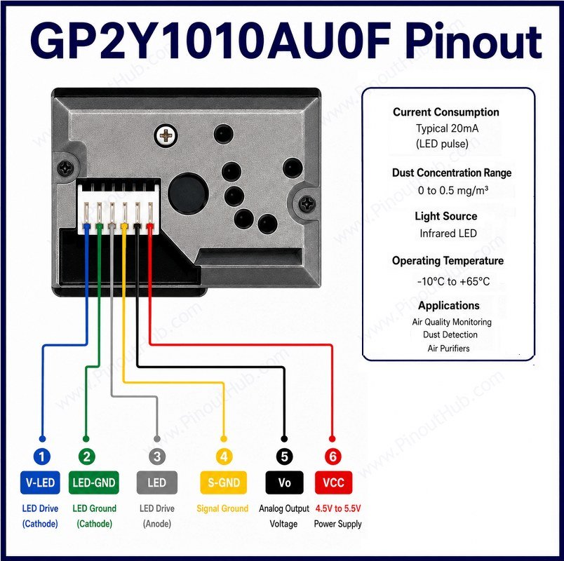
The GP2Y1010AU0F comes in a compact plastic housing with a 6-pin JST-style ribbon cable connector. Unlike bare ICs, it arrives pre-wired with a connector harness, making it easy to connect to a breadboard or prototype via jumper wires.
6-pin connector pinout
| Pin | Name | Type | Description |
|---|---|---|---|
| 1 | V-LED | Power | VCC for the internal IR LED — connect to 5V via a 150Ω series resistor |
| 2 | LED-GND | Power | Ground for the internal IR LED |
| 3 | LED | Input | Digital control pin to pulse the IR LED — connect to a microcontroller digital output |
| 4 | S-GND | Power | Ground for the sensor output circuit |
| 5 | Vout | Output | Analog voltage output proportional to dust concentration — connect to an ADC input |
| 6 | VCC | Power | Supply voltage for the sensor circuit — connect to 5V |
Working principle
The GP2Y1010AU0F uses optical light scattering to detect airborne dust. Air flows naturally through the sensing chamber via convection — there is no internal fan. Inside the chamber, the IR LED and phototransistor are positioned diagonally so their optical axes cross at the sensing zone. When a dust particle passes through this zone, it scatters infrared light toward the phototransistor. The more dust in the air, the more scattered light reaches the detector, and the higher the output voltage on Vout.
IR LED pulsing: The LED must be pulsed, not driven continuously. The correct timing sequence is: turn LED on → wait 0.28ms → sample Vout → wait 0.04ms → turn LED off → sleep for 9.68ms → repeat. This gives a total cycle of 10ms. Sampling outside this window produces inaccurate readings.
Baseline (Voc) management: The sensor produces a non-zero output voltage even in perfectly clean air, because a small amount of LED light reflects off the internal casing and reaches the phototransistor. This baseline is called Voc. To calculate actual dust density (ΔV), the application must store Voc in memory and subtract it from each reading. If a new reading Vo falls below the stored Voc, the lower value should replace it as the new Voc, accounting for gradual sensor cleaning or drift over time.
GP2Y1010AU0F Internal Construction
IR LED (Light Emitter) The infrared LED is the light source for the sensing system. A lens and slit assembly in front of it collimates and focuses the beam into a narrow spot at the crossing point inside the sensing chamber. It is pulsed at 10ms intervals with a 0.32ms pulse width to prevent overheating and to produce a clean, settled analog output for sampling.
Phototransistor (Light Detector) Positioned diagonally opposite the IR LED at approximately 45°. Its own lens and slit assembly narrows its acceptance angle, cutting out ambient light and making it sensitive only to light scattered sideways by particles in the sensing zone. The phototransistor never sees the LED’s direct beam — only scattered particle light.
Sensing Chamber / Air Inlet An open slot in the housing allows ambient air to enter and exit by natural convection. The crossing point of the LED beam and the phototransistor field of view defines the active sensing zone. Dust or smoke particles passing through this zone scatter IR light toward the detector.
Onboard Amplifier Circuit The phototransistor produces only a very weak current in response to scattered light. An internal op-amp circuit amplifies this into a 0–3.4V analog output range suitable for direct connection to a microcontroller ADC. The amplifier gain is factory-calibrated via an internal trimmer (VR) — the datasheet explicitly states this must not be adjusted in the field.
Lens and Slit Assembly Both the emitter and detector sides are fitted with a lens and slit. The emitter side focuses the LED output into a well-defined beam; the detector side limits the phototransistor field of view to the sensing zone only. Together they maximise sensitivity to particle scatter while minimising noise from ambient light and internal reflections.
Specifications
| Parameter | Value |
|---|---|
| Supply | |
| Supply Voltage (VCC) | 4.5V – 5.5V (5V typical) |
| Consumption Current (ICC) | 20mA max |
| Output | |
| Sensitivity (K) | 0.35 min / 0.5 typ V per 0.1 mg/m³ |
| Output Voltage – No Dust (Voc) | 0.9V typical / 1.5V max |
| Output Voltage High (VOH) | 3.4V typical |
| Output Interface | Analog voltage |
| LED | |
| LED Drive Current (ILED) | 11mA typical / 20mA max |
| LED Pulse Cycle | 10 ± 1ms |
| LED Pulse Width | 0.32 ± 0.02ms |
| Output Sampling Point | 0.28ms after LED turn-on |
| General | |
| Operating Temperature | −10°C to +65°C |
| Storage Temperature | −20°C to +80°C |
| Detection Target | Dust, cigarette smoke, fine particulate matter |
| Package | Plastic housing with 6-pin JST connector |
| RoHS | Compliant |
Helpful Resources
- Download the datasheet
- GP2Y1010AU0F with Arduino