The MPU6050 is a 6-axis inertial measurement unit (IMU) that combines a 3-axis gyroscope and a 3-axis accelerometer in a single compact chip. It is widely used in drones, self-balancing robots, motion-tracking systems, gaming controllers, and gesture-recognition devices.
By measuring both acceleration and rotational movement, the MPU6050 can determine an object’s orientation, tilt, and motion in real time. Its small size, low power consumption, and ease of interfacing with microcontrollers have made it one of the most popular motion sensors for embedded systems, robotics, and DIY electronics projects.
What is MPU6050?
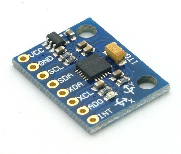
The MPU6050 combines a 3-axis gyroscope and a 3-axis accelerometer on the same silicon die, together with an onboard Digital Motion Processor (DMP) that processes complex 6-axis MotionFusion algorithms. The DMP incorporates InvenSense’s MotionFusion and run-time calibration firmware, eliminating the costly and complex selection, qualification, and system-level integration of discrete devices in motion-enabled products.
The MPU6050 supports I2C communications at up to 400kHz and has a VLOGIC pin that defines its interface voltage levels. It also exposes an auxiliary I2C bus that allows an external magnetometer or pressure sensor to be connected, with the DMP handling the fusion of all incoming data and presenting a unified output to the host — no intervention from the host processor required during operation.
MPU6050 overview
| Parameter | Value |
|---|---|
| Sensor Type | 6-Axis IMU (3-axis Gyroscope + 3-axis Accelerometer) |
| Supply Voltage (VDD) | 2.375V – 3.46V |
| Logic Level (VLOGIC) | 1.8V – VDD |
| Gyroscope Range | ±250, ±500, ±1000, ±2000 °/s (user-programmable) |
| Accelerometer Range | ±2g, ±4g, ±8g, ±16g (user-programmable) |
| ADC Resolution | 16-bit (gyroscope and accelerometer) |
| Output Type | Digital |
| Communication | I²C (up to 400kHz) |
| I²C Address | 0x68 (AD0 → GND) or 0x69 (AD0 → VDD) |
| Onboard DMP | Yes (Digital Motion Processor) |
| Temperature Sensor | Yes (onboard) |
| Shock Tolerance | 10,000g |
| Package | 4 × 4 × 0.9mm QFN (24-pin) |
| Compatible Boards | Arduino Uno, ESP32, Raspberry Pi |
Pinout
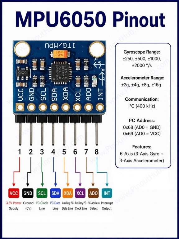
The bare MPU6050 IC is a 24-pin QFN and is not breadboard-compatible. It is almost always used on a breakout module with a standard 8-pin header.
Breakout Module Pinout (8-pin)
| Pin | Name | Type | Description |
|---|---|---|---|
| 1 | VCC | Power | Module supply — 3.3V or 5V (onboard regulator on most modules) |
| 2 | GND | Power | Ground |
| 3 | SCL | Input | I²C clock line |
| 4 | SDA | I/O | I²C data line |
| 5 | XDA | I/O | Auxiliary I²C data — for external magnetometer or sensor |
| 6 | XCL | Input | Auxiliary I²C clock — for external magnetometer or sensor |
| 7 | AD0 | Input | I²C address select — GND = 0x68, VDD = 0x69 |
| 8 | INT | Output | Interrupt output — goes HIGH when data is ready or threshold triggered |
Note: The AD0 pin selects the least significant bit of the I²C address. Connecting it to GND sets the address to 0x68; connecting it to VDD sets it to 0x69. This allows two MPU6050 modules to share the same I²C bus. If AD0 is left floating, the address defaults to 0x68.
Working principle
The MPU6050 contains two independent MEMS sensing elements — a gyroscope and an accelerometer — both feeding into shared 16-bit ADCs and a common digital interface.
Gyroscope Features three 16-bit ADCs for digitizing the gyroscope outputs and a user-programmable full-scale range of ±250, ±500, ±1000, and ±2000°/sec. The MEMS gyroscope measures angular rate — how fast the device is rotating around each of the X, Y, and Z axes. The output is in degrees per second (°/s), which can be integrated over time to derive angular position.
Accelerometer Features three 16-bit ADCs for digitizing the accelerometer outputs and a user-programmable full-scale range of ±2g, ±4g, ±8g, and ±16g. The accelerometer measures linear acceleration along each axis including the constant pull of gravity, making it useful for determining tilt and inclination even when the device is stationary.
Combining both: Neither sensor alone gives reliable orientation over time. The gyroscope drifts — small errors accumulate into large angular errors over seconds. The accelerometer is noisy during movement. The DMP and complementary/Kalman filter algorithms fuse both outputs to cancel each other’s weaknesses and produce stable, accurate orientation data.
Digital Motion Processor (DMP): The DMP processes complex 6-axis MotionFusion algorithms and can output data in rotation matrix, quaternion, or Euler Angle format. This offloads the sensor fusion computation entirely from the host microcontroller — particularly valuable on resource-constrained platforms like the Arduino Uno where floating-point quaternion math is expensive.
Sampling rates: The gyroscope samples at 8kHz internally. The accelerometer samples at 1kHz. Both can be further decimated by a programmable divider to any desired output rate from 3.9Hz up to the internal rate.
MPU6050 module hardware overview
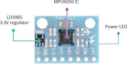
MPU6050 Sensor IC The small QFN chip at the centre of the board. Fabricated using InvenSense’s Nasiri-Fabrication platform, which integrates MEMS wafers with companion CMOS electronics through wafer-level bonding — driving the package size down to 4 × 4 × 0.9mm while providing 10,000g shock tolerance.
Both the gyroscope and accelerometer MEMS elements, their 16-bit ADCs, the DMP, temperature sensor, and I²C interface logic are all inside this one package.
3.3V Voltage Regulator Most breakout modules include an onboard LDO regulator that accepts 5V from the host board and steps it down to the 3.3V the MPU6050 IC requires. This is what allows the module to be powered directly from an Arduino 5V pin without damage.
Pull-up Resistors Hold the SDA and SCL lines at a high logic level when idle, as required by the I²C protocol. Included onboard so no external resistors are needed for standard I²C operation.
Bypass Capacitor (C1) A 100nF ceramic capacitor on the VLOGIC pin. The VLOGIC pin sets the logic reference voltage for the I²C pins — the bypass capacitor filters noise on this reference, which directly affects the digital output signal quality.
Decoupling Capacitors Filter high-frequency noise on the VDD supply rail. The MEMS elements are sensitive to supply noise, and the DMP’s internal clock — which maintains ±1% variation over the operating temperature range — requires clean power for consistent timing.
Specifications
The detailed specifications are listed below.
| Parameter | Value |
|---|---|
| Supply Voltage (VDD) | 2.375V – 3.46V |
| Logic Voltage (VLOGIC) | 1.8V – VDD |
| Supply Current (normal) | 3.9mA |
| Supply Current (sleep) | 5µA |
| Gyroscope Range | ±250 / ±500 / ±1000 / ±2000 °/s |
| Gyroscope Sensitivity (±250°/s) | 131 LSB/°/s |
| Gyroscope Sensitivity (±2000°/s) | 16.4 LSB/°/s |
| Gyroscope ADC Resolution | 16-bit |
| Gyroscope Internal Sample Rate | 8kHz |
| Gyroscope Zero-Rate Output | ±20°/s (max) |
| Gyroscope Noise Density | 0.005 °/s/√Hz |
| Accelerometer Range | ±2g / ±4g / ±8g / ±16g |
| Accelerometer Sensitivity (±2g) | 16384 LSB/g |
| Accelerometer Sensitivity (±16g) | 2048 LSB/g |
| Accelerometer ADC Resolution | 16-bit |
| Accelerometer Internal Sample Rate | 1kHz |
| Temperature Sensor Range | −40°C to +85°C |
| Temperature Sensitivity | 340 LSB/°C |
| Temperature Offset | −521 LSB at 35°C |
| I²C Speed | Up to 400kHz |
| I²C Address | 0x68 (AD0 = 0) or 0x69 (AD0 = 1) |
| Auxiliary I²C | Yes (XDA/XCL — for external sensors) |
| DMP FIFO Buffer | 1024 bytes |
| Programmable Low-Pass Filter | Yes (gyroscope, accelerometer, temperature) |
| Shock Tolerance | 10,000g |
| Onboard Oscillator Accuracy | ±1% over operating temperature |
| Package | 24-pin QFN |
| Dimensions | 4 × 4 × 0.9mm |
| Operating Temperature | −40°C to +85°C |
| RoHS | Compliant |
Helpful resources
- Download the datasheet here
- MPU6050 with Arduino
- MPU6050 with ESP32
- MPU6050 with the Raspberry Pi 4