The MQ135 is an analog air quality sensor by Winsen Electronics that detects a broad range of toxic and pollutant gases by measuring resistance changes across a heated tin dioxide element. Unlike the rest of the MQ series (which each target one or two specific gases), the MQ135 is designed as a general-purpose air quality indicator, sensitive to ammonia, sulfides, benzene series vapours, smoke, and other toxic gases simultaneously.
It is widely used in domestic air quality alarms, industrial pollution monitoring, and portable gas detectors where a quick overall measure of air contamination matters more than identifying a single specific gas.
What is MQ135?
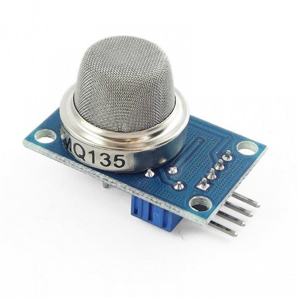
The sensitive material of the MQ135 gas sensor is SnO2, which has lower conductivity in clean air. When target pollution gas is present, the sensor’s conductivity increases along with the gas concentration rising. This change in conductivity is converted to a corresponding output signal through a simple circuit.
The MQ135 has high sensitivity to ammonia gas, sulfide, and benzene series steam, and can also monitor smoke and other toxic gases. It does not discriminate between individual gases — the output reflects the combined effect of all detectable pollutants present at once.
For applications that need to identify a specific gas by name or measure its concentration in ppm with accuracy, a dedicated single-gas sensor is more appropriate. For applications that simply need to know whether the air quality has degraded, the MQ135 is a practical and low-cost choice.
Note on CO2: The MQ135 is frequently described in tutorials as a CO2 sensor. This is misleading. The MQ135 is suitable for detecting NH3, NOx, alcohol, benzene, smoke, and CO2 — but its sensitivity to CO2 specifically is relatively low compared to dedicated NDIR CO2 sensors, and it cannot report CO2 concentration independently from other gases. It reacts to air quality deterioration broadly, not to CO2 exclusively.
MQ135 overview
| Parameter | Value |
|---|---|
| Sensor Type | Metal Oxide Semiconductor (MOS) Gas Sensor |
| Target Gas | Ammonia (NH3), Sulfide, Benzene series, Smoke, NOx |
| Detection Range | 10 – 1000 ppm (NH3, toluene, H2, smoke) |
| Circuit Voltage (VC) | 5.0V ±0.1V DC |
| Heater Voltage (VH) | 5.0V ±0.1V AC or DC |
| Heater Resistance | 30Ω ±3Ω (room temperature) |
| Heater Power Consumption | ≤950mW |
| Output Type | Analog (AO) + Digital TTL (DO) |
| Sensor Lifespan | 10 years |
| Operating Temperature | −10°C to +45°C |
| Communication | Analog Voltage / Digital Threshold |
| Mounting Type | Through Hole (6-pin bare sensor) |
| Compatible Boards | Arduino Uno, ESP32, Raspberry Pi |
Pinout

Breakout Module Pinout (4-pin)
| Pin | Type | Description |
|---|---|---|
| VCC | Power | Module supply — 5V |
| GND | Power | Ground |
| AO | Output | Analog output — voltage proportional to gas concentration (0V – 5V) |
| DO | Output | Digital TTL output — LOW when gas exceeds threshold, HIGH otherwise |
Working principle
The sensor requires two voltage inputs: heater voltage (VH) and circuit voltage (VC). VH supplies the standard working temperature to the sensor and can use DC or AC power. VC supplies the detection voltage to the load resistance RL in series with the sensor and must be DC.
As pollutant gas concentration rises, sensor resistance RS falls, and the output voltage on AO increases:
VOUT = VC × RL / (RS + RL)
The sensor resistance RS can be calculated from the measured output voltage using:
Rs = (Vc / VRL − 1) × RL
This RS value is then compared against the calibrated R0 (resistance in clean air) to derive a relative concentration using the sensitivity curves from the datasheet.
The output voltage in 400ppm H₂ under standard conditions is 2.0V to 4.0V, with a recommended load resistance of 4.7kΩ. The sensitivity is defined as Rs(air)/Rs(400ppm H₂) ≥ 5, and the concentration slope α ≤ 0.6 (R400ppm/R100ppm H₂).
Sensitivity to different gases (relative, from datasheet sensitivity curve):
| Gas | Relative Sensitivity |
|---|---|
| Ammonia (NH3) | High (primary target) |
| Hydrogen (H2) | High |
| Toluene | High |
| Smoke | Medium |
| Air | Baseline |
Warm-up requirement: Preheat time must be over 48 hours for first use. After storage: less than one month — no less than 48 hours; 1–6 months — no less than 72 hours; more than six months — no less than 168 hours.
MQ7 module components
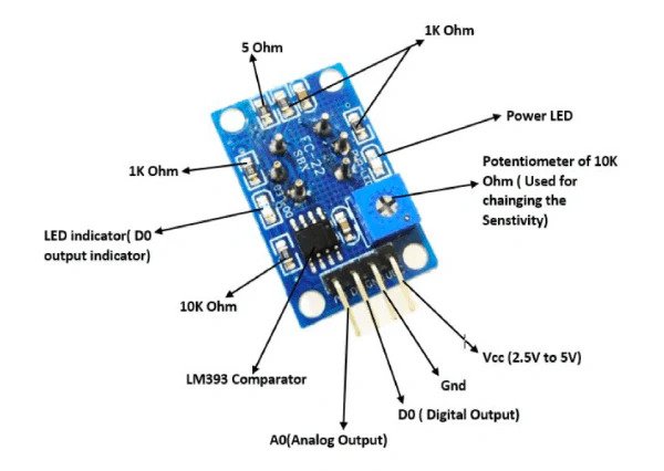
MQ135 Sensor Element The sensor is composed of a micro Al₂O₃ ceramic tube with a tin dioxide (SnO2) sensitive layer, measuring electrodes, and a heater coil, all fixed into a crust made of Bakelite and a metal cap. The metal cap allows ambient air and pollutant gases to reach the sensing surface while providing mechanical protection.
LM393 Voltage Comparator Converts the analog signal from the sensor into a digital TTL output. It compares the sensor voltage against the reference set by the potentiometer and switches DO LOW when the air quality threshold is exceeded.
Sensitivity Adjustment Potentiometer Sets the LM393 reference voltage, controlling the pollution concentration level at which DO triggers. Because the MQ135 responds to multiple gases simultaneously, the threshold should be set in the actual deployment environment rather than against a single reference gas for best results.
Power LED Illuminates when 5V is applied to VCC, confirming the module is powered and the heater coil is active.
Threshold LED Turns on when the DO pin triggers, providing immediate visual confirmation that air quality has fallen below the set threshold without requiring a microcontroller.
Decoupling Capacitors Filter noise on the 5V supply rail. The heater draws close to 190mA continuously, which can introduce supply ripple that affects analog output accuracy without proper filtering.
Specifications
| Parameter | Value |
|---|---|
| Target Gases | NH3, sulfide, benzene series, smoke, NOx |
| Detection Range | 10 – 1000 ppm (NH3, toluene, H2, smoke) |
| Circuit Voltage (VC) | 5.0V ±0.1V DC |
| Heater Voltage (VH) | 5.0V ±0.1V (AC or DC) |
| Heater Resistance | 30Ω ±3Ω (room temperature) |
| Heater Power Consumption | ≤950mW |
| Heater Current | ~190mA (typical at 5V) |
| Sensitivity (S) | Rs(air) / Rs(400ppm H₂) ≥ 5 |
| Output Voltage (Vs) | 2.0V – 4.0V (in 400ppm H₂) |
| Concentration Slope (α) | ≤0.6 (R400ppm / R100ppm H₂) |
| Recommended Load Resistance | 4.7kΩ (adjustable) |
| Analog Output (AO) | 0V – 5V |
| Digital Output (DO) | TTL — LOW when gas exceeds threshold |
| Comparator IC | LM393 |
| DO Threshold | Adjustable via onboard potentiometer |
| Preheat Time (first use) | ≥48 hours |
| Preheat Time (after 1–6 months storage) | ≥72 hours |
| Preheat Time (after 6+ months storage) | ≥168 hours |
| Minimum O₂ Concentration | 18% |
| Standard Test Temperature | 20°C ±2°C |
| Standard Test Humidity | 55% ±5% RH |
| Operating Temperature | −10°C to +45°C |
| Operating Humidity | <95% RH (non-condensing) |
| Sensor Lifespan | 10 years |
| Module Supply | 5V DC |
| Sensor Package | 6-pin through hole (Bakelite, metal cap) |
Helpful resources
- Download the datasheet here
- MQ135 with Arduino
- MQ135 with ESP32
- MQ135 with Pi Pico